COPYRIGHT
©
1999 CANON INC. CANON imageRUNNER 600 REV.1 JAN. 2000 PRINTED IN U.S.A.
8-5
CHAPTER 8 FIXING SYSTEM
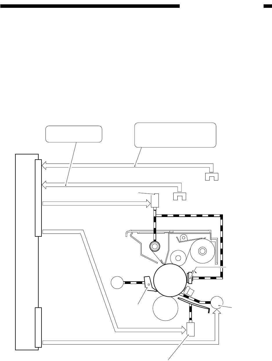
II . FIXING DRIVE SYSTEM
A. Outline
The fixing drive system is controlled for the following:
[1] Drive of the fixing roller.
[2] Drive of the cleaning belt.
[3] Drive of the fixing inlet guide.
[4] Drive of the thermistor reciprocating mechanism.
[5] Drive of the upper separation claw reciprocating mechanism.
Figure 8-201 Construction of the Control System
M3
M1
SL1
SL2
DC controller PCB
J508B
Drive signal
Detection signal
Detection signal
Drive signal
Drive signal
J508A
Inlet guide drive solenoid
Fixing roller
motor
Thermistor
Upper
separation
claw
Main motor
Cleaning belt drive solenoid
PS7
Web absent sensor
PS8
Web absent
warning sensor
Issues an error upon
detection.
Indicates that the cleaning
belt is running out on the
control panel upon detection.


