


CHAPTER 6 IMAGE FORMATION SYSTEM
6-8
COPYRIGHT
©
1999 CANON INC. CANON imageRUNNER 600 REV.1 JAN. 2000 PRINTED IN U.S.A.
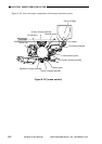
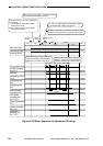
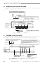
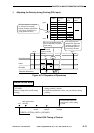
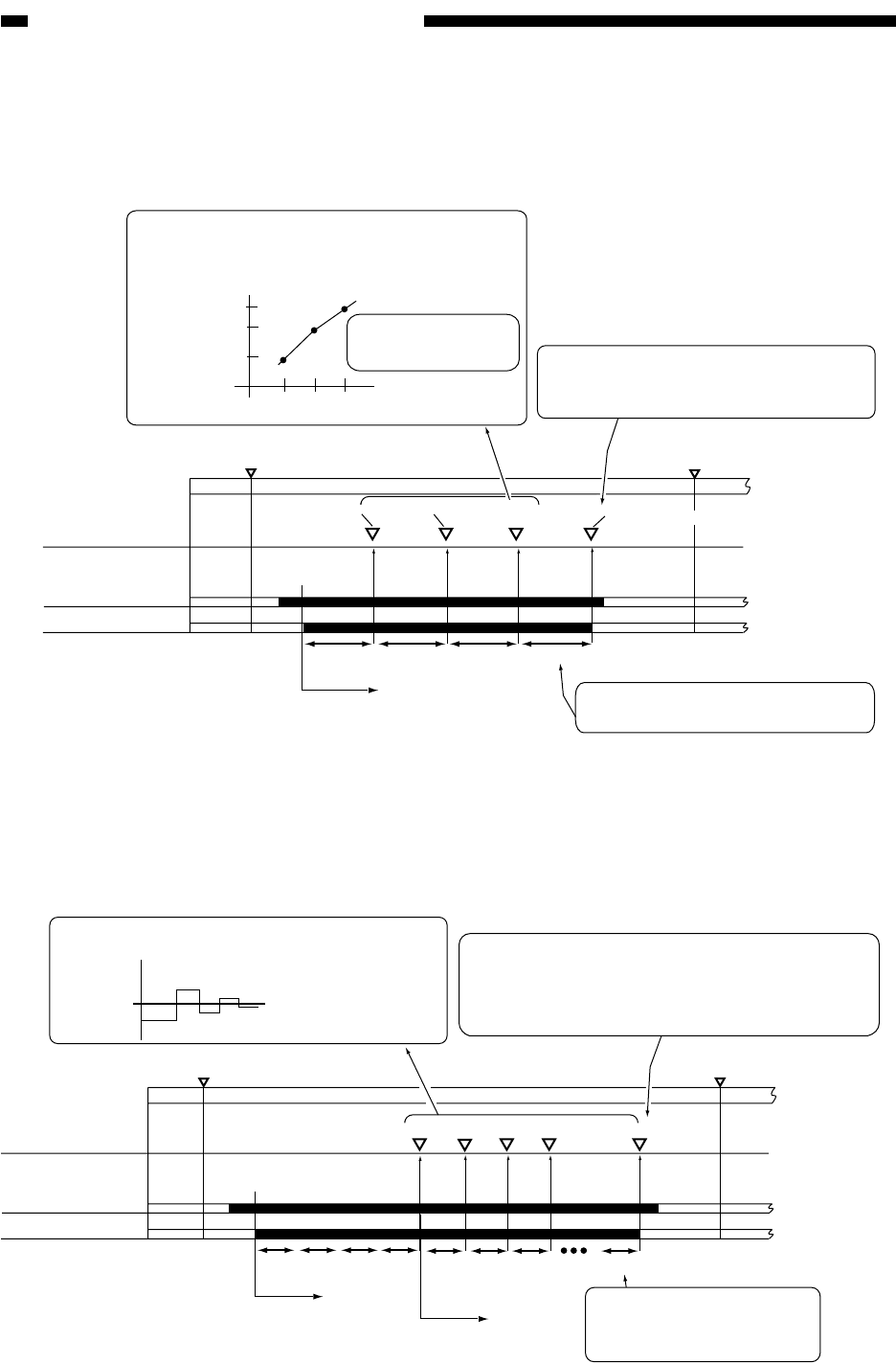
B. Determining the Optimum Grid Bias
A grid bias is selected so that the surface potential of the drum will be identical to the target
potential (the primary charging bias is fixed).
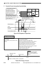
C. Grid Bias Corrective Control
If an optimum grid bias cannot be selected after measuring the surface potential of the drum
several times, a corrective control sequence is started to determine the optimum grid bias.
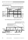
WMUPR
WMUP
STBY
195˚C
200˚C
Potential sensor
Grid bias
500 V 600 V 700 V
Measurement
(VD1)
Measurement
(VD2)
Measurement
(VD3)
Vg
500V
600V
700V
VD1
VD2
VD3
Grid bias
If the target VD is attained basde on this
measurement, control is ended; otherwise,
corrective control will start.
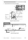
The relationship between the surface potential of
the drum (VD) and the gird bias is obtained based
on measurements taken several times.
Charging
characteristic curve
A grid bias (VG) needed to attain the
target VD is selected.
Potential control
sequence started
Primary charging
bias (DC)
Measurement
(targetVD)
Figure 6-205 Sequence of Operations (corrective control)
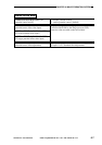
WMUPR
WMUP
STBY
195˚C
200˚C
Grid bias
500V
600V
700V
Vg
Vg1 Vg2 Vg3 Vg8
VD1
VD-NG
VD2
VD3
VD-NG
VD1
VD2 VD3
VD8
Target VD
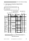
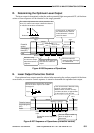
Measurement is continued while varying the level of
the grid bias so as to attain the target VD.
If the measurement is identical to the target VD,
control is ended. Measurements are taken as many
as 8 times; at times, an approximate level (to the
target VD) may be used.
Primary charging
bias (DC)
Potential control
sequence started
Corrective control
sequence started
The grid bias (vg) needed to
attain the target VD is
determined.
Potential
sensor
Figure 6-204 Sequence of Operations