CHAPTER 9 EXTERNALS/AUXILIARY MECHANISMS
9-22
COPYRIGHT
©
2000 CANON INC. CANON imageRUNNER 600 REV.1 JAN. 2000 PRINTED IN U.S.A.
2. Operation
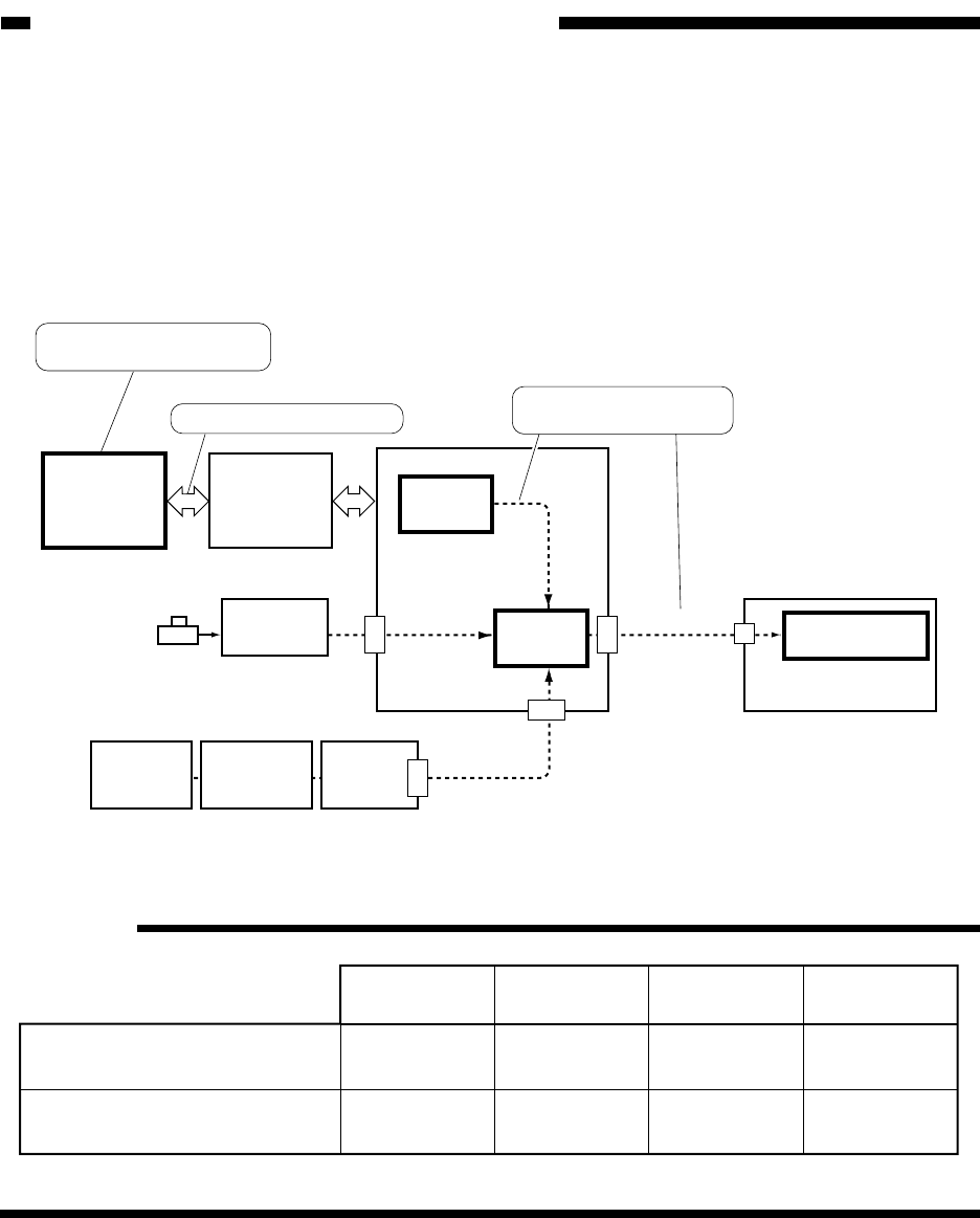
a. Shift from Standby to Sleep Mode
The timer on the MFC PCB keeps track of lapses of time, and it issues a sleep mode shift
command when a specific period of time passes. In response to the sleep shift command, the DC
controller PCB causes the DC_POWER_OFF signal to go '0' and the A_REMOTE signal to go '0'.
In response to the A_REMOTE signal=0, the relay circuit switches the power supply to sleep
mode.
Figure 9-602 Shift to Sleep Mode
Reference:
DC
controller
PCB
Control
panel
CPU PCB
Control
panel power
switch
A-REMOTE
Switching
circuit
MFC
PCB
System
motherboard
Remote signal
control assembly
J1407
J525
J505
J503
J1719
3
A31
A11
B12
B31
Relay PCB
CPU
IC18
MFC
PCB
Image
processor
PCB
DC_POWER_OFF
Sleep mode shift command
When the signal goes '0',
shift to sleep mode.
Printer
PCB
(accessory)
Keeps track of lapses of
time for sleep mode.
100V/20A
model
100V/15A
model
120V model 230V model
359 355
12
335 330
12 12 16
Standby power consumption
(Wh)
Sleep mode power consumption
(Wh)
The heater switch is off, and printer mode is not available.


