CHAPTER 8 FIXING SYSTEM
8-6
COPYRIGHT
©
1999 CANON INC. CANON imageRUNNER 600 REV.1 JAN. 2000 PRINTED IN U.S.A.
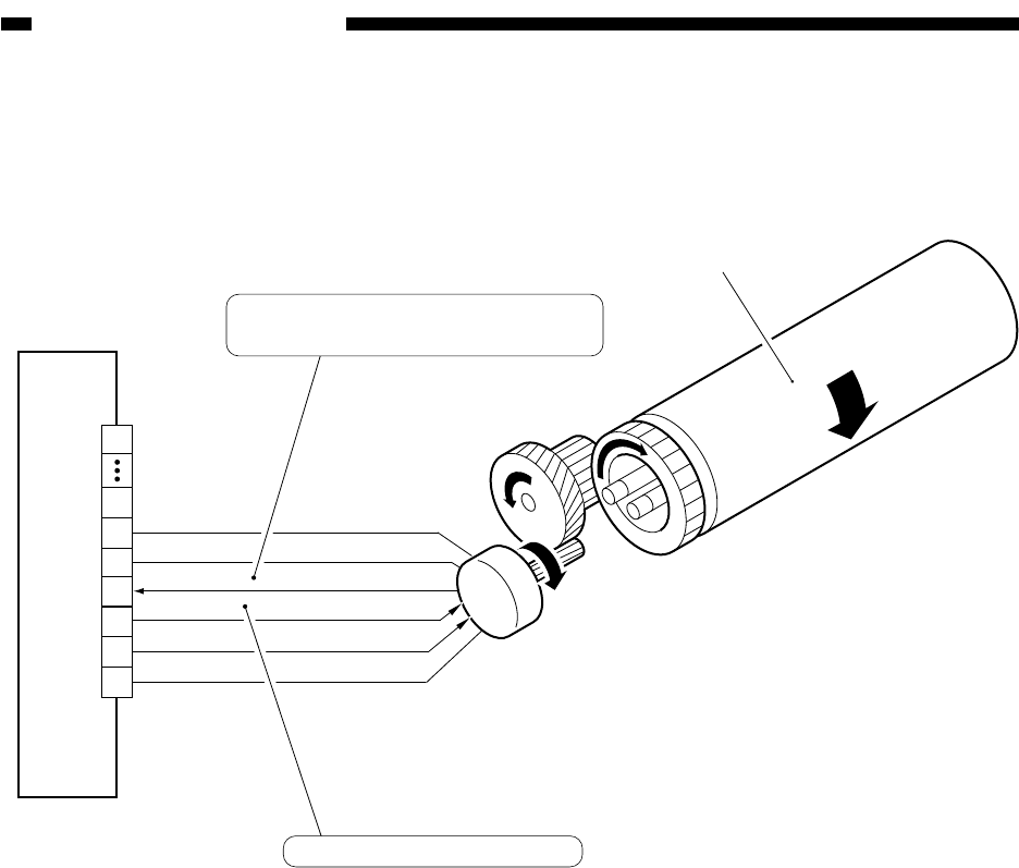
B. Controlling the Fixing Roller Drive Mechanism
Figure 8-202 shows the construction of the control system used to control the fixing roller
drive mechanism.
Figure 8-202 Construction of the Control System
DC controller PCB
J508A
15
1
16
17
18
19
20
FXM-LCK
0V
0V
0V
5V
FXM-ON
14
M3
Upper fixing roller
Fixing drive motor
When the rotation speed of the fixing
motor reaches a specific value, '0'.
When '1', the motor turns on.


