


CHAPTER 13 TROUBLESHOOTING
13-166
COPYRIGHT
©
2000 CANON INC. CANON imageRUNNER 600 REV.1 JAN. 2000 PRINTED IN U.S.A.
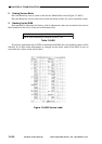
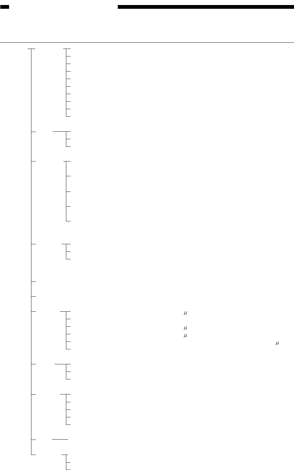
Items under COPIER>DISPLAY
Level 1 Level 2 Level 3 Description
DISPLAY VERSION DC-CON Indicates the version of the ROM on the DC controller PCB.
IP Indicates the version of the ROM on the image processor PCB.
FEEDER Indicates the version of the ROM on the feeder controller PCB.
SOR
Indicates the version of the ROM on the sorter controller PCB.
PC/PCL Indicates the version of the ROM on the PC/PCL controller PCB.
LIPS Indicates the version of the ROM on the LIPS controller PCB.
MFC Indicates the version of the ROM on the MFC PCB.
PCL Indicates the version of the ROM on the PCL controller PCB.
PS/KANJI Indicates the version of the ROM on the PS/KANJI controller PCB.
SDL-STCH Indicates the version of the ROM on the saddle stitcher controller PCB.
USER LANGUAGE Indicates the language used.
COUNTER Indicates the count control type for the copy counters.
MODEL Indicates the model.
ANALOG TEMP Indicates the machine temperaure humidity (detected by the
environment sensor).
HUM Indicates the machine internal humidity (detected by the environment
sensor).
OPTICS Indicates the temperature of the scanning lamp (detected by the
fluorescent lamp temperature sensor H5).
FIX-C Indicates the temperature at the middle of the upper fixing roller
(detected by the main thermistor TH1).
FIX-E Indicates the temperature of the ends of the upper fixing roller
(detected y the sub thermistor TH2).
CST-STS WIDTH-C3 Indicates the paper size for the cassette 3.
WIDTH-C4 Indicates the paper size for the cassette 4.
WIDTH-MF Indicates the paper width (new value) or the paper size for the manual
feed tray.
JAM Indicates the jam history.
ERR Indicates the error history.
HV-STS PRIMARY Indicates the current level (
A) of the primary charging assembly.
PRI-GRID Indicates the grid voltage (V) of the primary charging assembly.
PRI-TR Indicates the current level ( A) of the pre-transfer charging assembly.
TR Indicates the current level ( A) of the transfer charging assembly.
SP Indicates the current level of the separation charging assembly ( A).
BIAS Indicates the voltage of the developing DC bias (V).
DPOT DPOT-K Indicates the surface potential (V) of the photosensitive drum.
VL1M Indicates the drum light area potential measurement (V).
VDM Indicates the drum dark area potential measurement (V).
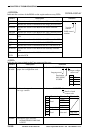
SENSOR DOC-SZ Indicates the size of an original detected by the original size sensor.
DOC-SZ1 Indicates the output of the original size sensor 1.
DOC-SZ2 Indicates the output of the original size sensor 2.
DOC-SZ3 Indicates the output of the original size sensor 3.
DOC-SZ4 Indicates the output of the original size sensor 4.
MISC FL-LIFE Indicates the activation duty ratio (%) of the scanning lamp.
ALARM1 BODY Indicates alarm codes.
DF Indicates alarm codes.
SORTER Indicates alarm codes.