COPYRIGHT
©
1999 CANON INC. CANON imageRUNNER 600 REV.1 JAN. 2000 PRINTED IN U.S.A.
6-25
CHAPTER 6 IMAGE FORMATION SYSTEM
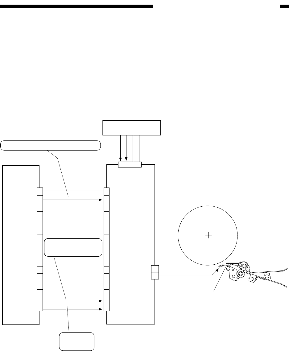
Figure 6-307 Construction of the Control System
D. Controlling the Transfer Guide Bias
1. Outline
To prevent soiling of the surface of the transfer guide with toner (leading to soiled backs), a
bias of the same polarity as toner is applied to the transfer guide. The transfer guide charging
mechanism is controlled for the following:
[1] Transfer guide bias constant voltage
[2] Output to suit the environment
Figure 6-307 shows the construction of the transfer guide bias
DC controller PCB
J510A
DC 600V/200V
J723
1
2
3
4
5
6
7
8
9
10
11
12
13
14
15
16
1
2
3
4
5
6
7
8
9
10
11
12
13
14
15
16
0 V
24 VH
24 VH
HVDC-EN
FGD-ON
GND
GND
1
2
3
4
Relay PCB
Transfer guide
J733
1
2
FGD-CNT
High-voltage DC PCB
When '1', high voltage output is ready.
When '1', the transfer
guide bias turns on.
'1' : +200V
'0' : +600V


