CHAPTER 8 FIXING SYSTEM
8-18
COPYRIGHT
©
1999 CANON INC. CANON imageRUNNER 600 REV.1 JAN. 2000 PRINTED IN U.S.A.
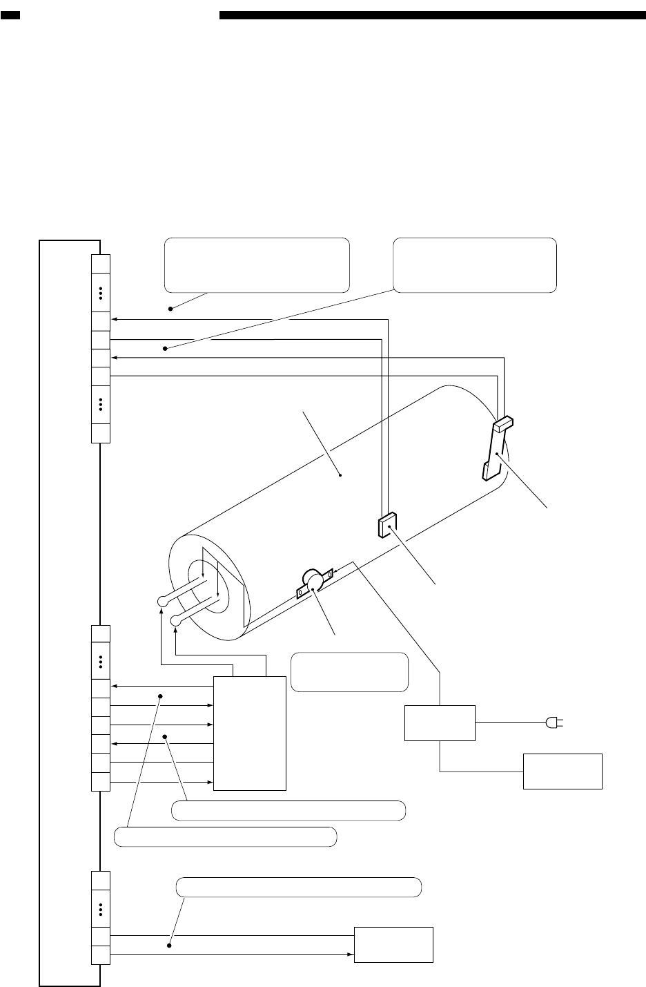
D. Error Detection
The fixing temperature control mechanism is monitored for the following:
[1] Temperature control error by the main thermistor (TH1; see the sequence charts on the
pages that follow)
[2] Sensor error by the sub thermistor (TH2; see the sequence charts on the pages that follow)
[3] Overheating error by the thermal switch (TP1)
Figure 8-305 Construction of the Control System
DC controller PCB
J508B
1
7
8
10
20
S-TEMP
0V
0V
M-TEMP
Upper fixing roller
Main
heater
Sub thermistor
Main thermistor
Thermal switch
9
J505A
11
10
0V
24V
MHDTC
SHDTC
SH-ON
14
J512A
1
14
13
24V
SW-OFF
RLY
Relay
Front door
SSR
Main switch
12
13
Sub heater
MH-ON
9
1
Voltage suited to the
temperature detected by the
main thermistor
Voltage suited to the
temperature detected by
the sub thermistor
At 223˚C, the AC
line is turned off
When '1', the main heater turns on.
When the sub heater is powered, '0'.
When '0', the main switch is turned off.


