COPYRIGHT
©
2000 CANON INC. CANON imageRUNNER 600 REV.1 JAN. 2000 PRINTED IN U.S.A.
5-5
CHAPTER 5 LASER EXPOSURE SYSTEM
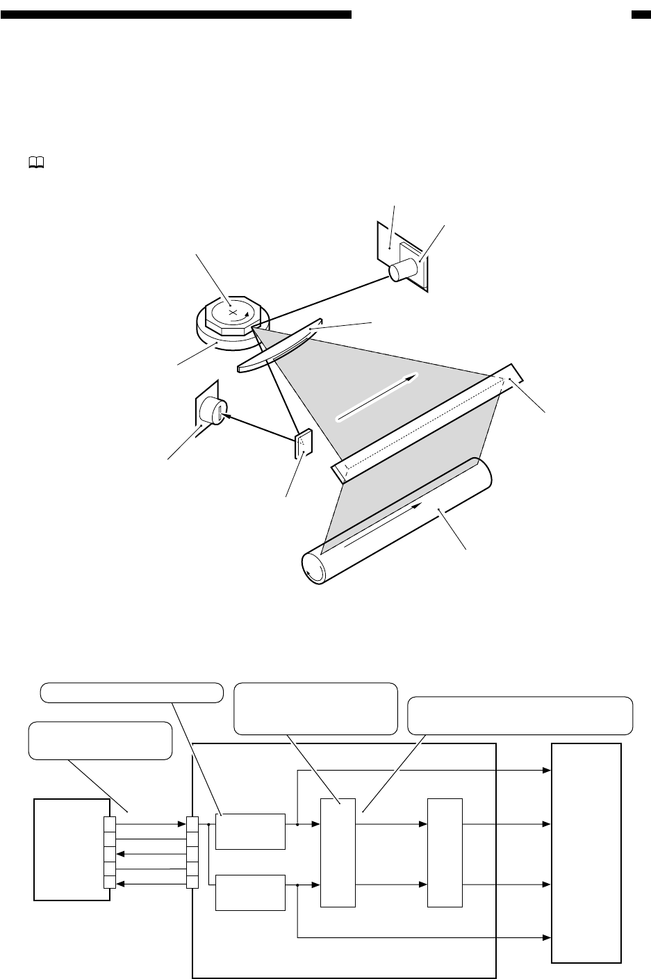
II . GENERATING THE BD SIGNAL
A. Outline
Part 2>Chapter 4>2
Figure 5-201 Construction of the Control System
B. Flow of the BD Signal
Figure 5-202 Flow of Signals
Photosensitive drum
BD PCB
BD mirror
8-facet mirror
Laser scanner motor
Imaging lens
Laser unit
Laser mirror
Laser driver PCB
BD
detection
PCB
Image processor PCB
BD-SGNL
J3701
GND
5V
GND
-5V
PSYNC-B
VIDEO-B
VIDEO-A
CLK-B
CLK-A
PSYNC-A
5
4
3
2
1
1
2
3
4
5
CLK-B
generation
Laser
driver
CLK-A
generation
Memory control
Sync signal
generation
Reads from memory based on this
sync signal.
Generates sync signals
for the printer based
on CLK-B.
Clock pulses for the printer
When the laser beam
is detected, '1'.


