


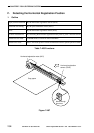
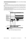
CHAPTER 7 PICK-UP/FEEDING SYSTEM
7-36
COPYRIGHT
©
1999 CANON INC. CANON imageRUNNER 600 REV.1 JAN. 2000 PRINTED IN U.S.A.
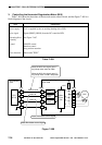
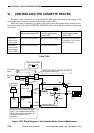
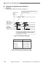
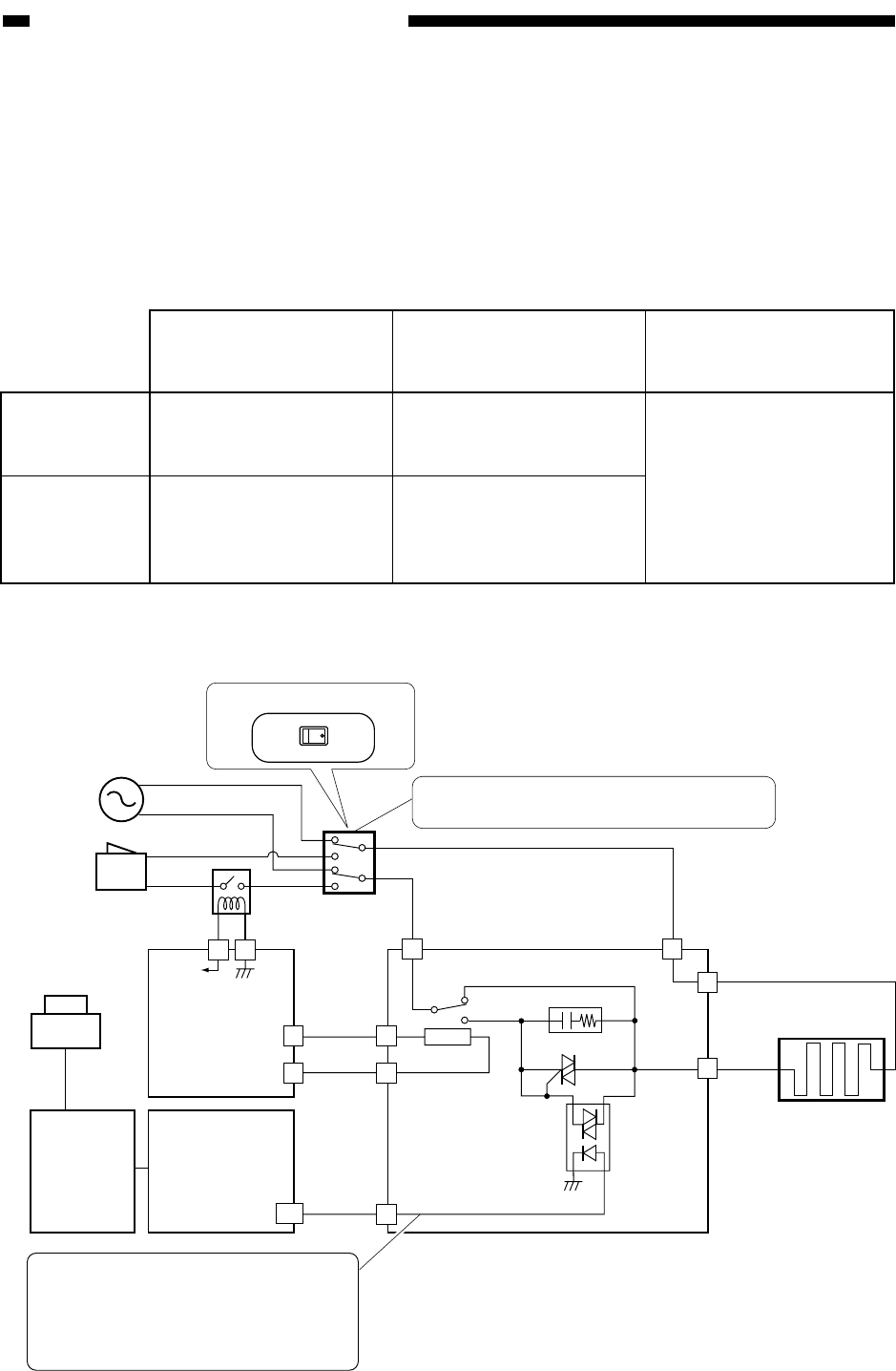
VI . CONTROLLING THE CASSETTE HEATER
The drive of the cassette heater is synchronized with either the outlet power supply or the
control panel power switch, selected by the heater switch (SW3).
While the copier is operating (i.e., both power switch and control panel power switch are on),
the cassette heater ON signal (CASSETTE_HEATER_ON) controls the drive of the cassette heater
at all times.
Table 7-601
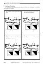
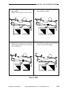
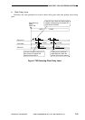
Figure 7-601 Block Diagram of the Cassette Heater Control Mechanisms
4
4
4
3
2
3
1
A8
J2601
J2604
1
J2605
J2601
J2602
J2602
GND
24V
Relay PCB
DC controller
PCB
MFC
PCB
Control panel
power switch
Cassette heater
(H4)
Q2604
Q2603
Z2602
RLY2602
J505
J1722
J1722
24V
Heater drier PCB
CASETTE_HEAT_ON
3
Heater switch
(SW3)
31
Main power
switch
From power
outlet
Relay
(RLY2)
Selects either power outlet sync or control
panel power switch sync.
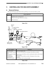
OFF ON
Heater switch (SW3)
When the cassette heater ON signal
goes '1', the cassette heater turns on.
When making double-side copies in a
low-humidity environment, '0';
otherwise, '1'.
Sync with
outlet power
supply (ON)
Sync with
control panel
paper supply
switch (OFF)
Main power switch OFF
Drives the cassette heater.
Stops the cassette heater.
Main power switch ON
Control panel power
switch OFF
Drives the cassette heater.
Stops the cassette heater.
Main power switch ON
Control panel power
switch ON
Drives the cassette heater
in response to the cassette
heater ON signal.