11-34
COPYRIGHT
©
1999 CANON INC. CANON imageRUNNER 600 REV.1 JAN. 2000 PRINTED IN U.S.A.
CHAPTER 11 INSTALLATION
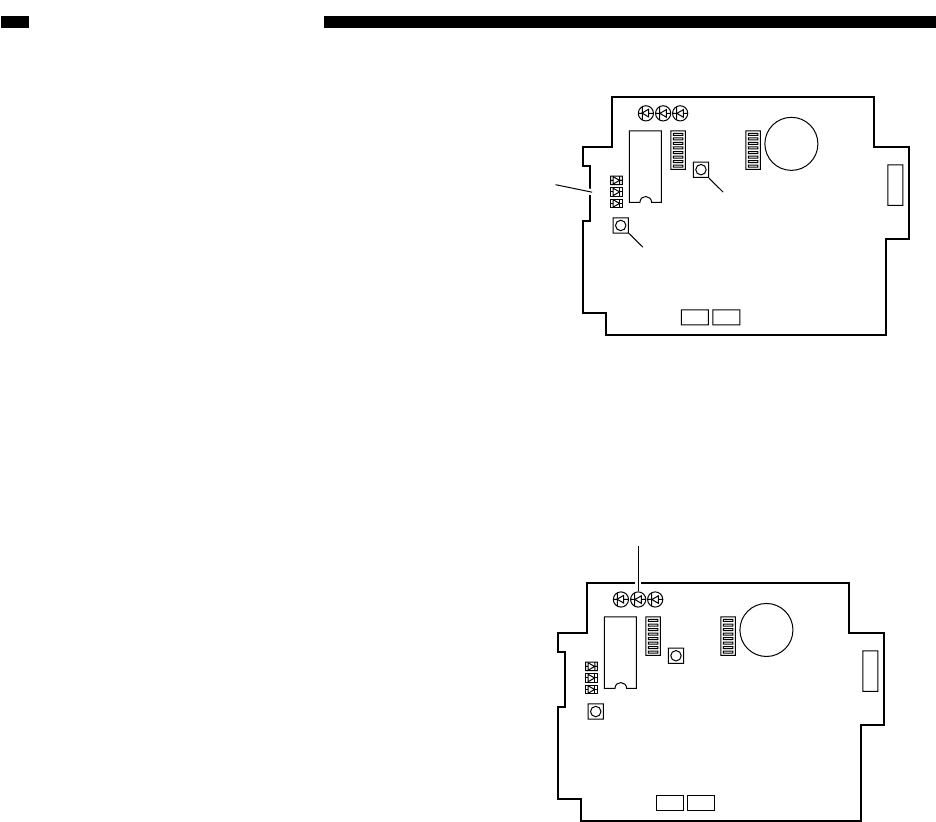
Figure 11-517
Figure 11-516
LED1 LED2LED3
2
1
LED5
LED6
LED4
IC6
SW1
SW4
SW3
6
1
BAT1
CN4
1
2
CN3 CN2
SW2
[22]
[16]
[23]
17) Check to find out if the controller is ca-
pable of calling the service station. Press
the push switch SW4 [16] on the PCB of
the controller.
In response, LED6 [22] (red) should turn
on; it should turn off to indicate the end of
transmission, and should flash if the trans-
mission ends in failure.
If LED6 [22] is flashing, press the push
switch SW4 [16] once again to try re-
transmission.
If the push switch SW1 [23] is pressed
while LED6 [22] is flashing, on the other
hand, the controller cancels transmission
attempts.
18) Check to make sure that the communica-
tion between the controller and the copier
is normal.
Connect the copier's power plug, and turn
on the power switch; then, check to see
that LED2 [24] (orange) flashes.
LED1 LED2
LED3
2
1
LED5
LED6
LED4
IC6
SW1
SW4
SW3
6
1
BAT1
CN4
1
2
CN3 CN2
SW2
[24]


