COPYRIGHT
©
1999 CANON INC. CANON imageRUNNER 600 REV.1 JAN. 2000 PRINTED IN U.S.A.
6-13
CHAPTER 6 IMAGE FORMATION SYSTEM
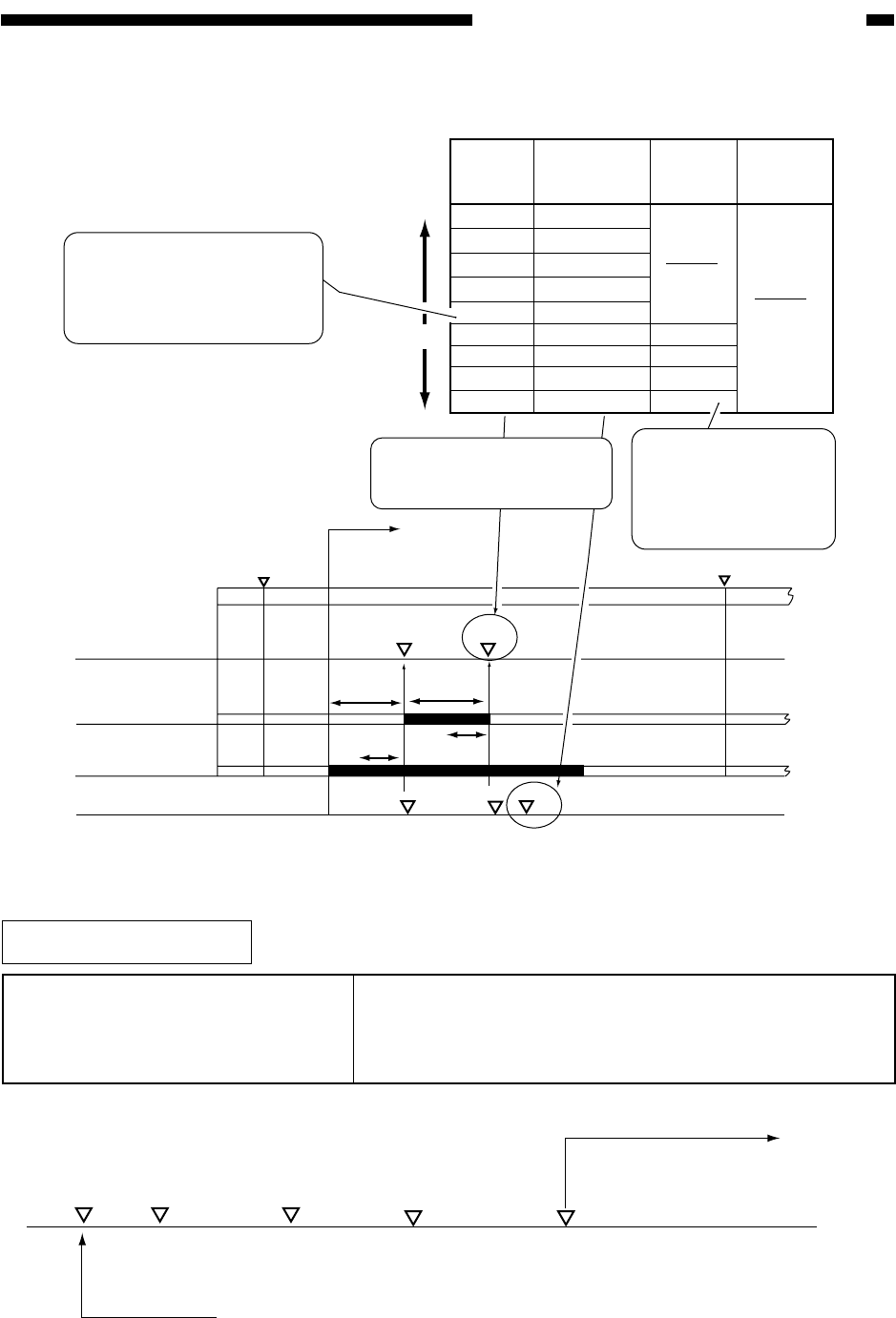
Figure 6-211 Sequence of Operations
Table 6-202 Timing of Control
1. Adjusting the Density during Printing (PDL input)
WMUPR
WMUP
STBY
195˚C
200˚C
Potential sensor
Laser
Grid bias
Vg
Vg
Pw
Pw
Vdc
VD
VL
Potential determined
1
2
3
4
5
6
7
8
9
x0.8
x0.9
x1.0
x1.1
x1.2
x1.3
x1.4
x1.5
x1.5
+40V
+30V
+20V
+10V
F value
Density
Darker
Lighter
The laser power is increased
(to increase the contrast),
thereby enabling reproduction
of fine lines narrower than a
single particle of toner.)
The laser power/developing
bias is corrected to suit the F
value setting.
The laser power has
reached the upper limit,
requiring correction of
the developing bias to
increase the contrast.
Laser power
correction
value
Vdc
correction
value
VD
correction
value
Potential control
sequence started
COPIER>OPTION>BODY>
CNT-W/PR
(density setting mode on/off during
printing)
1: correct the target value to enable variation of density
during printing. (default)
0: disable the mechanism used to vary the density during
printing.
Related Service Mode
COPIER > OPTION > BODY > CNT-W/PR
Set
Potential
control
Printing
started
Main power switch
OFF/ON
F value
changed
A laser power output Vdc
suited to the F value setting
is used.


