CHAPTER 9 EXTERNALS/AUXILIARY MECHANISMS
9-8
COPYRIGHT
©
1999 CANON INC. CANON imageRUNNER 600 REV.1 JAN. 2000 PRINTED IN U.S.A.
B. Sequence of Operations
1. 2-Speed Control
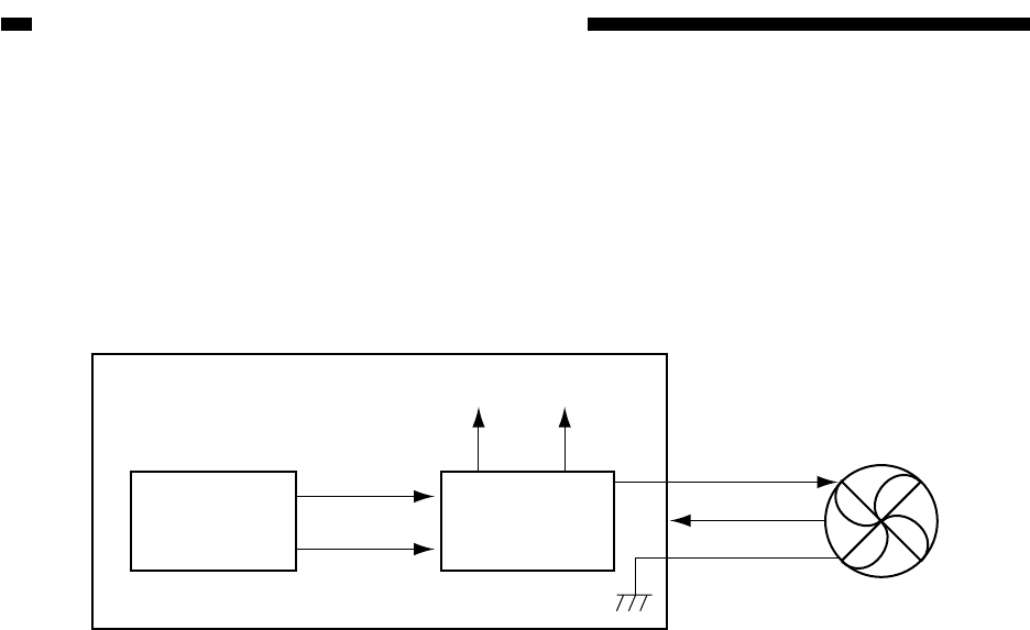
Some of the copier's fans are designed for 2-speed control (Table 9-401). The speed is switched
by the voltage switching circuit of each fan by switching voltage levels.
Some fans are controlled according to the state of the printer, while some are controlled by the
state of the scanning lamp.
Figure 9-402 2-Speed Control Block Diagram
Voltage
switching circuit
CPU
DC controller PCB
Fan
24V or 12/18V
Clock signal
Full-speed
signal
Half-speed
signal
24V 12/18V
In the case of FM2, the voltage is reduced to 18 V during half-speed rotation.


