CHAPTER 7 PICK-UP/FEEDING SYSTEM
7-34
COPYRIGHT
©
1999 CANON INC. CANON imageRUNNER 600 REV.1 JAN. 2000 PRINTED IN U.S.A.
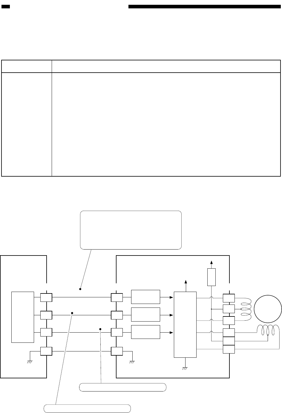
3. Controlling the Horizontal Registration Motor (M15)
Table 7-404 shows the functions of the reversal motor control circuit, and the Figure 7-409 is a
block diagram of the circuit.
Table 7-404
Figure 7-409
+24V
A
A*
B
B*
M15
B4
B5
B3
B2
B6
B1
FU3
A1
A2
A3
A4
A8
A7
A6
A5
J3602J519 J3603
SREJI-HOLD
SREJI-B
SREJI-A
+24V
Motor
driver
(IC2)
DC controller
PCB
No-stacking feeding
driver PCB
Interface
circuit
Interface
circuit
Interface
circuit
CPU
(IC13)
When the M15 drive signal goes '1',
the pickup motor starts to rotate.
When the M15 drive signal goes '0',
the pickup motor is held in stop state.
Phase-B excitation control signal
Phase-A excitation control signal
Description
24 V is supplied by the no-stacking feeding driver PCB.
Signal (SREGI_HOLD) from the DC controller PCB.
See Figure 7-407.
ON/OFF control
Rotation control
Stop position retention
Error code "E051"
Item
Power supply
Drive signal
Operating/drive
assembly
Control
Error detection


