


COPYRIGHT
©
2000 CANON INC. CANON imageRUNNER 600 REV.1 JAN. 2000 PRINTED IN U.S.A.
9-9
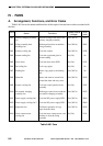
CHAPTER 9 EXTERNALS/AUXILIARY MECHANISMS
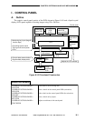
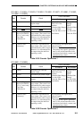
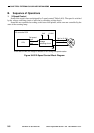
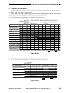
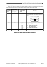
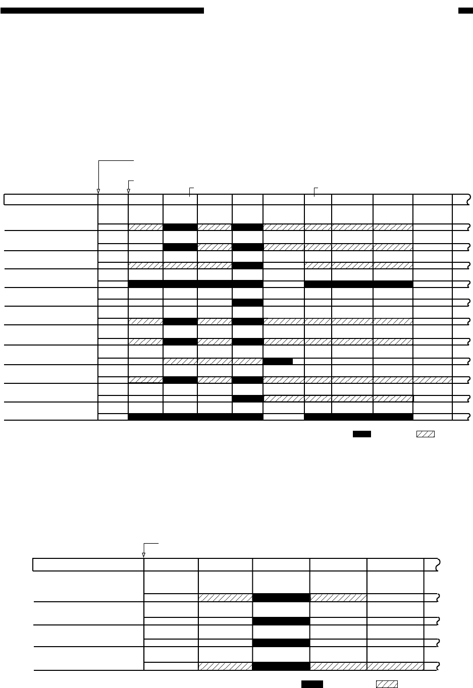
2. Sequence of Operations
The fans operate as follows, ones controlled according to the state of the printer and ones
controlled by the state of the scanning lamp:
(FM3, FM11, and FM12 operate based on the state of both the printer unit and the scanning
lamp, and the control mechanism for higher speed is used for the chart.)
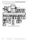
a. Fans Operating According to the State of the Printer Unit
Figure 9-403
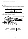
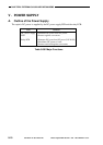
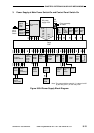
b. Fans Operating According to the State of the Scanning Lamp
Figure 9-404
Control panel
switch ON
Main power
switch ON
Primary charging
assembly fan (FM1)
Drum fan (FM8)
Pre-transfer charging
assembly fan (FM10)
Feeding fan (FM7)
Scanner cooling fan
(FM3)
Fixing assembly heat
discharge fan (FM2)
Laser driver cooling
fan (FM5)
Separation fan (FM13)
Power supply cooling
fan 1/2 (FM11, FM12)
Laser scanner motor
cooling fan (FM14)
De-curling fan (FM6)
Warm-up
Printer unit
Initialmultiple rotation
Standby Copying
Pre-heating
Door openJam ErrorAfter copying
15 min
15 min
: full speed. : half speed.
Warm-up: Until the temperature of the fixing assembly reaches 195˚C.
Intial multiple rotation: After the temperature of the fixing assembly has
reached 200˚C until potential control ends.
Scanning lamp cooling fan
(FM3)
Power supply cooling fan
1/2 (FM11, FM12)
Stream reading fan (FM4)
Inverter cooling fan (FM9)
Scanning lamp
Off On Pre-heating Error
Main power
switch ON
: full speed. : half speed.