CHAPTER 5 LASER EXPOSURE SYSTEM
5-8
COPYRIGHT
©
1999 CANON INC. CANON imageRUNNER 600 REV.1 JAN. 2000 PRINTED IN U.S.A.
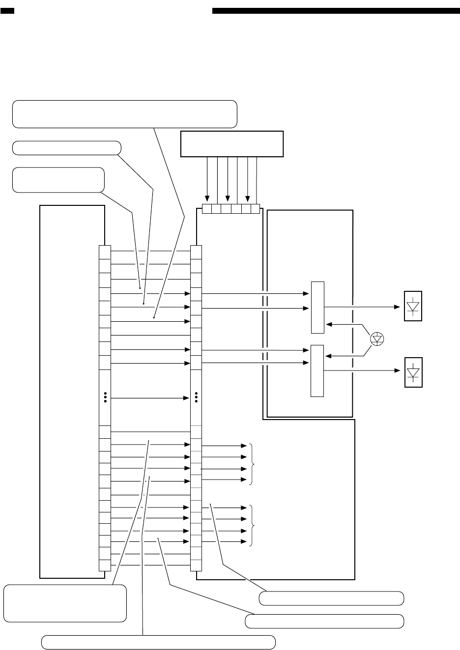
B. Controlling Laser Activation
Figure 5-301B shows the construction of the system used to control laser activation.
Figure 5-301B Construction of the Control System
Image processor PCB
J1107
1
2
3
4
5
6
7
8
9
10
18
19
20
21
22
23
24
25
26
28
30
29
27
1
2
3
4
5
6
7
8
9
10
18
19
20
21
22
23
24
25
26
28
30
29
27
GND
GND
GND
GND
GND
SH-D-B
RST-B
Not used
Not used
SH-D-A
BSH-B
BSH-A
SH-B
SH-A
RST-A
LD-DWN
LD-EN-B
LD-EN-A
LD-OFF-B
LD-OFF-A
Not used
Laser driver PCB 2
Laser driver PCB 1
1
2
3
4
5
6
Relay PCB
5V
8V
-8V
GND
GND
GND
J1714
J1301
J1354
LD-B
LD-A
Laser B
Laser A
Intensity monitor
Intensity control signal
To LD-A/B
To LD-A/B
When the laser OFF signal is '1' , the laser turns off.
Sampling during wait activation
Sampling during imaging activation
This signal is used to decrease the laser intensity
between sheets to prolong the life of the laser.
When the laser activation
prohibit signal is
'1', activation is disabled.
Reset signal per scan.
Laser activation
signal for sampling


