


COPYRIGHT
©
1999 CANON INC. CANON imageRUNNER 600 REV.1 JAN. 2000 PRINTED IN U.S.A.
CHAPTER 6
IMAGE FORMATION SYSTEM
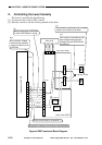
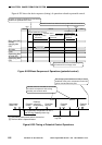
This chapter provides descriptions on the copier's image processing operations,
functions of each operation, relationships between electrical and mechanical
systems, and timing at which each associated part is turned on.
I . PROCESSES ............................. 6-1
A. Outline ................................... 6-1
B. Basic Sequence of Operations
(image formation) .................. 6-3
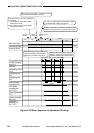
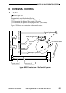
II . POTENTIAL CONTROL ............. 6-5
A. Outline ................................... 6-5
B. Determining the Optimum Grid
Bias ....................................... 6-8
C. Grid Bias Corrective Control .. 6-8
D. Determining the Optimum Laser
Output.................................... 6-9
E. Laser Output Corrective Control
.............................................. 6-9
F. Determining the Optimum
Developing Bias .................. 6-10
G. Potential Control for
Transparency Mode ............ 6-11
H. Target Potential Correction in
Each Mode ..........................6-12
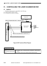
III . CONTROLLING THE CHARGING
MECHANISMS ......................... 6-16
A. Controlling the Primary Charging
Mechanism .......................... 6-16
B. Dust-Collecting Roller Bias .. 6-20
C. Controlling the Pre-Transfer
Charging Mechanism .......... 6-21
D. Controlling the Transfer Guide
Bias ..................................... 6-25
E. Controlling the Transfer Charging
Mechanism .......................... 6-27
F. Controlling Separation Charging
............................................ 6-32
IV . DEVELOPING ASSEMBLY...... 6-36
A. Outline ................................. 6-36
B. Controlling the Developing
Assembly ............................. 6-37
C. Controlling the Toner Cartridge
Drive Mechanism................. 6-38
D. Controlling the Developing Bias
............................................ 6-39
E. Detecting the Toner Level and
Controlling the Toner Supply
Mechanism .......................... 6-41
V . DRUM CLEANER UNIT ........... 6-45
A. Outline ................................. 6-45
B. Detecting the Waste Toner (case
full condition) .......................6-46
VI. CONTROLLING THE DRUM
HEATER ................................... 6-48
A. Outline ................................. 6-48
VII .DISASSEMBLY/ASSEMBLY .... 6-49
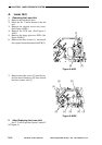
A. Photosensitive Drum Unit .... 6-50
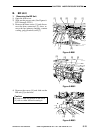
B. Parts Associated with the
Process Unit ........................ 6-55
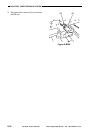
C. Charging Wire ..................... 6-60
D. Process Unit ........................ 6-66
E. Developing Assembly .......... 6-69
F. Drum Cleaner Unit............... 6-75
G. Separation Claw/Separation
Claw Drive Assembly........... 6-79