COPYRIGHT
©
1999 CANON INC. CANON imageRUNNER 600 REV.1 JAN. 2000 PRINTED IN U.S.A.
5-3
CHAPTER 5 LASER EXPOSURE SYSTEM
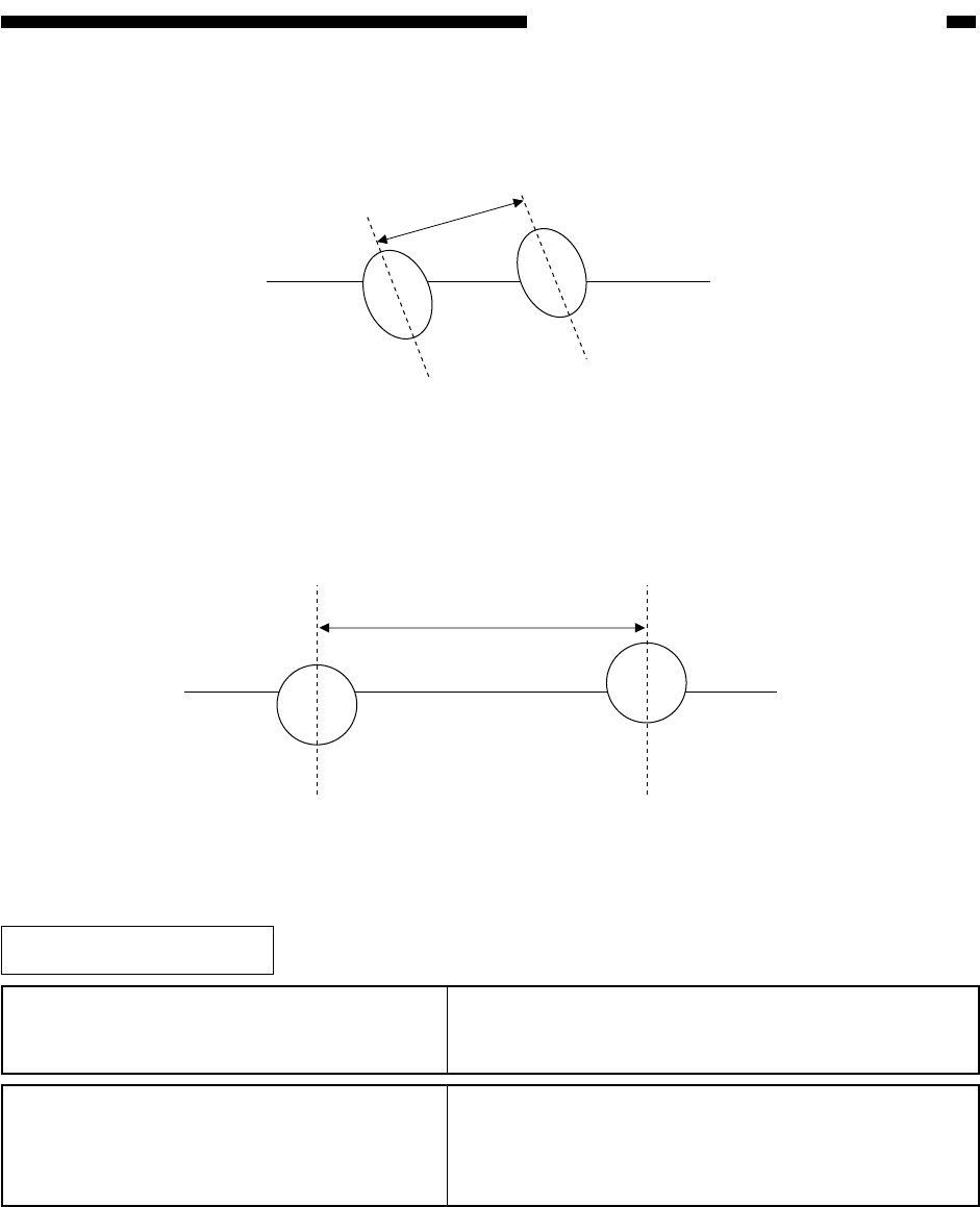
The laser A and the laser B have a discrepancy of 80 µm (between light-emitting sections) as
follows:
Figure 5-102
A delay is initiated in the image signals on the image processor PCB to generate a delay of 760
µm (equivalent of 18 pixels) at time of scanning the drum, thereby preventing interference of laser
beams.
Figure 5-103
80µm
760µm (18 pixels)
Related Service Mode
COPIER>ADJUST>LASER>IP-DELAY
(image processor PCB display input)
If you have replaced the image processor PCB or
initialized the RAM on the image processor PCB, enter
the values recorded on the label attached to the PCB.
COPIER>ADJUST>LASER>LA-DELAY
(laser unit delay value input)
If you have replaced the laser unit or the image
processor PCB, or if you have initialized the RAM on
the image processor PCB, enter the value recorded on
the label attached to the laser unit.


