COPYRIGHT
©
1999 CANON INC. CANON imageRUNNER 600 REV.1 JAN. 2000 PRINTED IN U.S.A.
11-23
CHAPTER 11 INSTALLATION
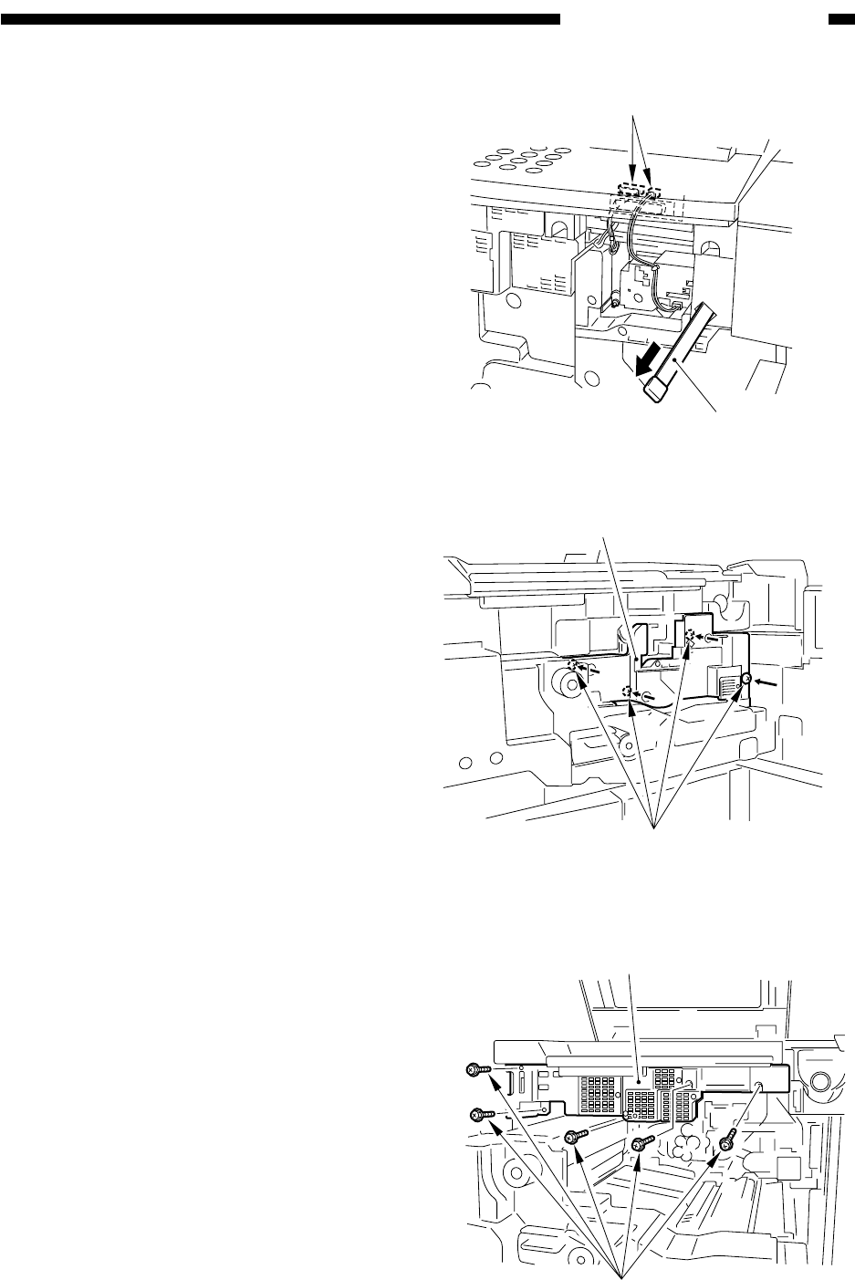
3) Disconnect the two connectors, and de-
tach the dust-proofing glass.
4) Slide out the feeding assembly.
5) Remove the four screws, and detach the
process unit cover.
6) Remove the five screws, and detach the
inside cover (upper).
Figure 11-403
Figure 11-404
Connectors
Dust-proofing glass
Figure 11-405
Process unit cover
Screws (to prevent displacement)
Inside cover (upper)
Screws


