


High-performance Embedded Workshop 6. I/O File Format
REJ10J1837-0100 Rev.1.00 Nov. 16, 2008
408
6. I/O File Format
High-performance Embedded Workshop formats the IO window based on information it finds in an I/O Register
definition file. When you select a debugging platform, High-performance Embedded Workshop will look for a
“<device>.IO” file corresponding to the selected device and load it if it exists. This file is a formatted text file that
describes the I/O modules and the address and size of their registers. You can edit this file, with a text editor, to add
support for memory mapped registers or peripherals you may have specific to your application e.g. registers in an ASIC
device mapped into the microcomputer's address space.
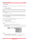
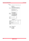
File format
Each module name must be defined in the Modules definition section and the numbering of each module must be
sequential. Each module corresponds to a register definition section and within the section each entry defines an I/O
register.
The BaseAddress definition is for devices where the location of I/O registers moves in the address space depending on
the CPU mode. In this case, the BaseAddress value is the base address of the I/O registers in one specific mode and the
addresses used in the register definitions are the address locations of the registers in the same mode. When the I/O
register file is actually used, the BaseAddress value is subtracted from the defined register address and the resultant
offset added to the relevant base address for the selected mode.
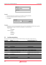
Each module has a section that defines the registers forming it along with an optional dependency, the dependency is
checked to see if the module is enabled or not. Each register name must be defined in the section and the numbering of
each register must be sequential. The dependency is entered in the section as dep=<reg> <bit> <value>.
1. <reg> is the register id of the dependency.
2. <bit> is the bit position within the register.
3. <value> is the value that the bit must be for the module to be enabled.
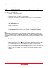
The [Register] definition entry is entered in the format id=<name> <address> [<size>
[<absolute>[<format>[<bitfields>]]]].
1. <name> register name to be displayed.
2. <address> address of the register.
3. <size> which may be B, W or L for byte, word, or long word (default is byte).
4. <absolute> which can be set to A if the register is at an absolute address. This is only relevant if the I/O area
address range moves about on the CPU in different modes. In this case, if a register is defined as absolute the
base address offset calculation is not performed and the specified address is used directly.
5. <format> Format for register output. Valid values are H for Hexadecimal, D for decimal, and B for binary.
6. <bitfields> section defining the bits within the register.
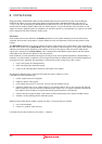
Bitfield sections define the bits within a register each entry is of the type bit<no>=<name>.
1. <no> is the bit number.
2. <name> is a symbolic name of the bit.
Comment lines are allowed and must start with a “;” character.