


TMP92CZ26A
92CZ26A-109
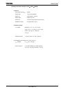
Sample 5) Calculation example when using CPU + LCDC + SDRAMC + HDMA
at same time (Worst case)
Conditions:
CPU operation speed (f
SYS
) : 80MHz
Display RAM : Internal RAM
Display size : QVGA (320seg
× 240com)
Display quality : 16777216 color (TFT)
Refresh rate : 70Hz
HDMA : Transfers 225 Kbytes from internal RAM to SDRAM
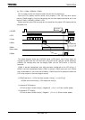
Calculation example:
t
STOP
(LCD) = ((SegNum × K/8) × t
LRD
) + (1/f
SYS
[Hz])
= ((320 × 24/8) × 1/f
SYS
[Hz]/4) + (1/f
SYS
[Hz])
= ((960) × 12.5 [nS]/4) + 12.5 [nS]
= 3.0125 [μS]
LHSYNC [period: S]
= 1/70 [Hz]/ (COM+20) = 54.9 [μS]
t
STOP
(HDMA) = (((2 + 1) × 4) × 57600) + 28800 + 14400)/f
SYS
[S] = 9180 [μS]
LCD driver data transfer time [S]
= SegNum × (1/fsys) × (LD bus transfer speed)
= 320 × (1/80MHz) × 8 = 32 [μS]
LHSYNC [cycle S] - LCD driver data transfer time [S]
− t
STOP
(LCD)
= 54.9 [μS] − 32 [μS] − 3.0125 [μS] = 19.8875 [μS]
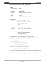
To realize proper LCD display, the maximum time HDMA can occupy the bus at a time (maximum HDMA time)
must be set to 19.8875 [
μS] or less. Although transferring all 225 Kbytes from the internal RAM to SDRAM requires t
STOP
(HDMA) = 9180 [
μs], the maximum HDMA time should be limited by using the HDMATR register.
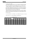
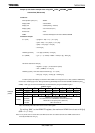
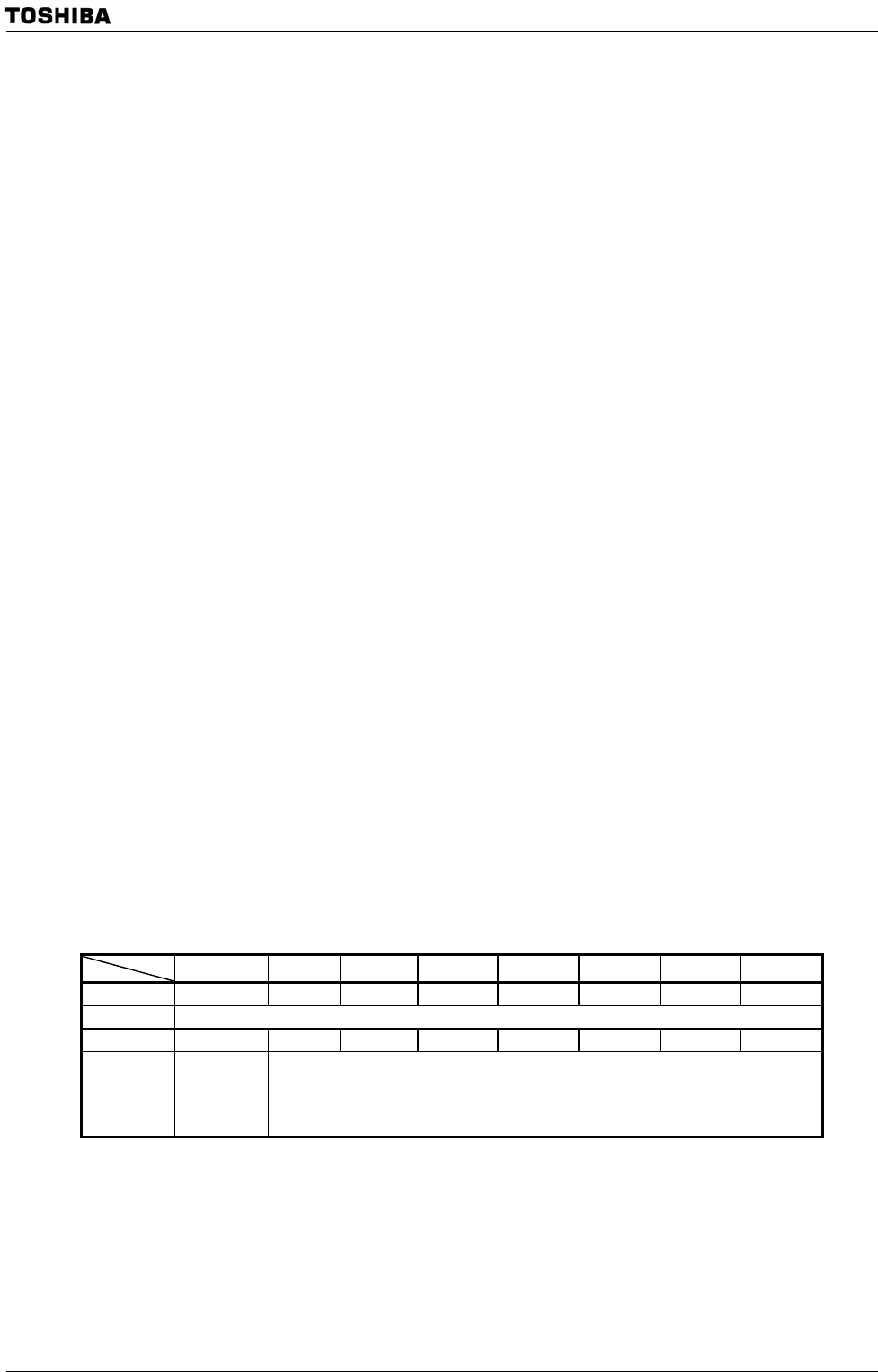
HDMATR register
7 6 5 4 3 2 1 0
Bit Symbol
DMATE DMATR6 DMATR5 DMATR4 DMATR3 DMATR2 DMATR1 DMATR0
Read/Write
R/W
After reset
0 0 0 0 0 0 0 0
Function
Timer
operation
0: Disable
1:Enable
Maximum bus occupancy time setting
The value to be set in <DMATR6:0> should be obtained by
“Maximum bus occupancy time / (256/f
SYS
)”.
“00H” cannot be set.
Note: Read-modify-write instructions can be used on this register.
By writing “86H” to the HDMATR register, the maximum HDMA time is set to 19.2[μs]
(256 × 6 × (1 / f
SYS
)).
Note: To be precise, the bus assert time and RAM access time are added each time the HDMA transfer time is
forcefully terminated at 19.2 [
μs].
HDMATR
(097FH)