


TMP92CZ26A
92CZ26A-359
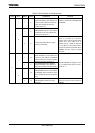
(3) 1-word Data Transfer
Check the <MST> by the INTSBI interrupt process after the 1-word data transfer is
completed, and determine whether the mode is a master or slave.
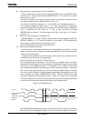
a. If <MST> = “1” (Master Mode)
Check the <TRX> and determine whether the mode is a transmitter or
receiver.
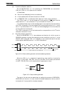
When the <TRX> = “1” (Transmitter mode)
Check the <LRB>. When <LRB> is “1”, a receiver does not request data.
Implement the process to generate a stop condition (Refer to 3.15.6 (4)) and
terminate data transfer.
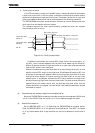
When the <LRB> is “0”, the receiver is requests new data. When the next
transmitted data is 8 bits, write the transmitted data to SBIDBR. When the next
transmitted data is other than 8 bits, set the <BC2:0> <ACK> and write the
transmitted data to SBIDBR. After written the data, <PIN> becomes “1”, a serial
clock pulse is generated for transferring a new 1-word of data from the SCL pin,
and then the 1-word data is transmitted. After the data is transmitted, an
INTSBI interrupt request occurs. The <PIN> becomes “0” and the SCL line is
pulled down to the Low-level. If the data to be transferred is more than one word
in length, repeat the procedure from the <LRB> checking above.
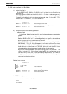
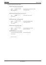
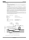
INTSBI interrupt
if MST = 0
Then shift to the process when slave mode
if TRX = 0
Then shift to the process when receiver mode.
if LRB = 0
Then shift to the process that generates stop condition.
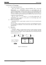
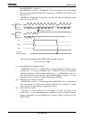
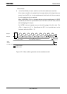
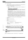
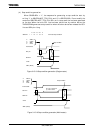
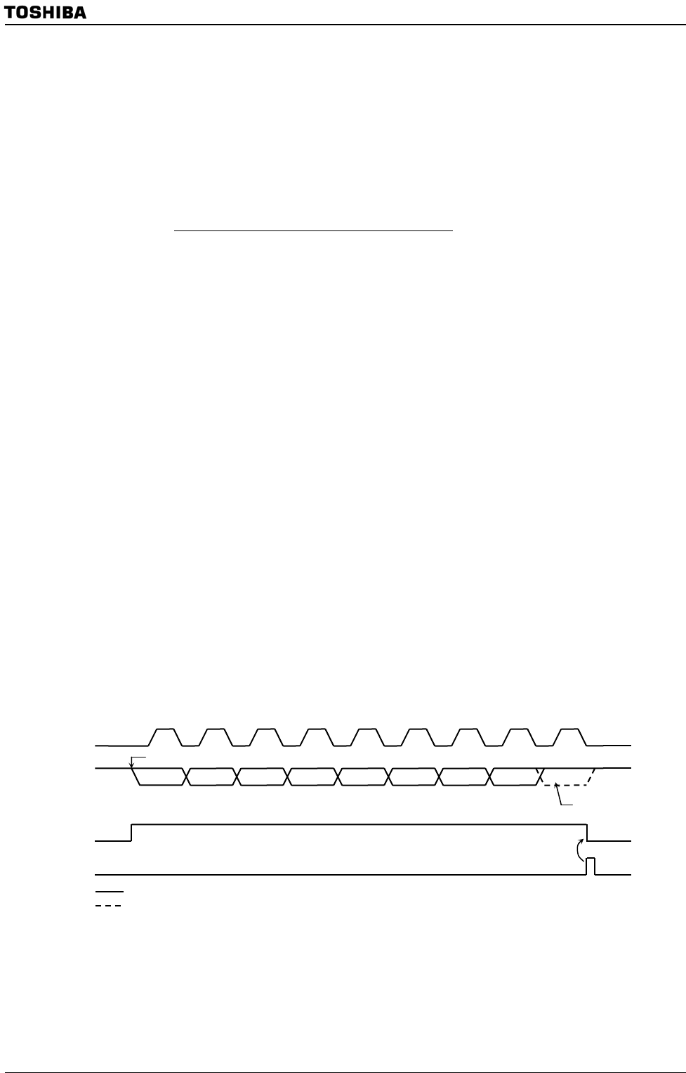
Figure 3.15.15 Example in which <BC2:0> = “000” and <ACK> = “1” in transmitter mode
7 6 5 4 3 2 1 0
SBICR1
←
X X X X X X X X Set the bit number of transmit and ACK.
SBIDBR
←
X X X X X X X X Write the transmit data.
End of interrupt
Note: X: Don’t care
1
2 3 45678 9
D7 D6 D5 D4 D3 D2 D1 D0
A
cknowledge
signal from a
receiver
Write to SBIDBR
SCL
SDA
<PIN>
INTSBI
interrupt request
ACK
Output from master
Output from slave