


TMP92CZ26A
92CZ26A-191
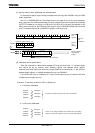
(4) Wait control
The external bus cycle completes for two states minimum(25 ns at f
SYS
= 80 MHz).
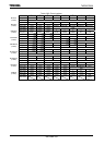
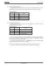
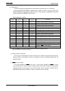
Setting the BnCSL<BnWW3:0> specifies the number of waits in the write cycle, and
BnCSL<BnWR3:0> specifies the number of waits in the read cycle. <BnWW3:0> is set with
the same method as <BnWR3:0> as follows;
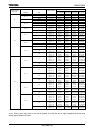
BnCSL<BnWW>/<BnWR>
<BnWW3>
<BnWR3>
<BnWW2>
<BnWR2>
<BnWW1>
<BnWR1>
<BnWW0>
<BnWR0>
Function
0 0 0 1 2 states (0 waits) access fixed mode
0 0 1 0 3 states (1 wait) access fixed mode (Default)
0 1 0 1 4 states (2 waits) access fixed mode
0 1 1 0 5 states (3 waits) access fixed mode
0 1 1 1 6 states (4 waits) access fixed mode
1 0 0 0 7 states (5 waits) access fixed mode
1 0 0 1 8 states (6 waits) access fixed mode
1 0 1 0 9 states (7 waits) access fixed mode
1 0 1 1 10 states (8 waits) access fixed mode
1 1 0 0 11 states (9 waits) access fixed mode
1 1 0 1 12 states (10 waits) access fixed mode
1 1 1 0 14 states (12 waits) access fixed mode
1 1 1 1 18 states (16 waits) access fixed mode
0 1 0 0 22 states (20 waits) access fixed mode
0 0 1 1
6 states +
WAIT pin input mode
others (Reserved)
Note 1:For SDRAM, above setting is ineffective. Refer to the section 3.18 SDRAM controller.
Note 2:For NAND flash, this setting is ineffective.
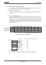
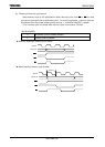
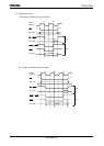
(i) Waits number fixed mode
The bus cycle is completed with the set states. The number of states is selected from 2
states (0 waits) to 12 states (10 waits), 14 states(12 waits), 18 states(16 waits) and 22
states(20 waits).
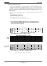
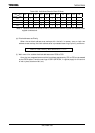
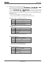
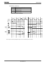
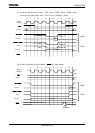
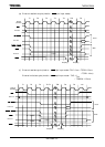
(ii)
WAIT
pin input mode
This mode samples the
WAIT
input pins. It continuously samples the
WAIT
pin state
and inserts a wait if the pin is active. The bus cycle is minimum 6 states. The bus cycle is
completed when the wait signal is non active (“High” level) at 6 states. The bus cycle is
extended as long as the wait signal is active in case more than 6 states.