


TMP92CZ26A
92CZ26A-48
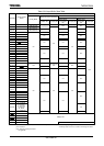
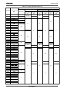
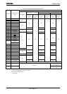
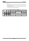
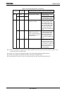
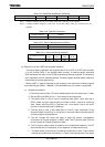
Table 3.4.4 Recommended Pin Connections
Recommended Pin Connections for Each Download Method
Port Name
Function
Name
I/O
UART USB
P90 TXD0 Output No special setting is needed
for booting via USB.
UART
P91 RXD0 Input
Connect to the level shifter.
Add a pull-up resistor (100
kΩ recommended) to prevent
transition to UART processing.
−−− D+ I/O No special setting is needed
for booting via UART.
Connect to the USB connector
by adding a dumping resistor
(27Ω recommended) and a
programmable pull-up resistor
(1.5 kΩ recommended). When
USB is not accessed, the pin
level should be fixed with a
resistor to prevent flow-through
current.
−−− D− I/O
If USB is not used, add a
pull-up or pull-down resistor to
prevent flow-through current
on the D+/D- pins.
Connect to the USB connector
by adding a dumping resistor
(27Ω recommended). When
USB is not accessed, the pin
level should be fixed with a
resistor to prevent flow-through
current.
USB
PU6 PUCTL Output
−
This pin is used to control
ON/OFF of the D+ pin’s
pull-up resistor. Add a switch
externally so that the pull-up is
turned on when “1”. Reset sets
this pin as an input port, so
add a pull-down resistor (100
kΩ recommended).
Note 1: When a user program is downloaded from UART and USB is used in the system, the pull-up resistor for USB’s D+ pin
should not be turned on in BOOT mode.
Note 2: When a user program is downloaded via USB, do not start the UART application software on the PC.
Note 3: When a user program is downloaded via UART, do not connect a USB connector.
Note 4: When USB is not used, the D+ and D- pins must be pulled up or down to prevent flow-through current.