


TMP92CZ26A
92CZ26A-52
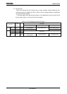
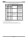
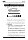
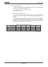
Table 3.4.8 Baud Rate Modification Command
Baud Rate (bps) 9600 19200 38400 57600 115200
Modification Command 28H 18H 07H 06H 03H
Note 1: If f
OSCH
(oscillation frequency) is 10.0 MHz, 57600 and 115200 bps are not supported.
Note 2: If f
OSCH
(oscillation frequency) is 6.00, 8.00, or 9.00 MHz, 38400, 57600, and 115200 bps are not
supported.
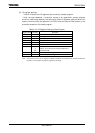
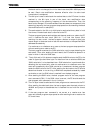
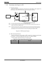
Table 3.4.9 Operation Command
Operation Command Operation
C0H User program start
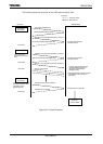
Table 3.4.10 Version Management Information
Version Information ASCII Code
FRM1 46H, 52H, 4DH, 31H
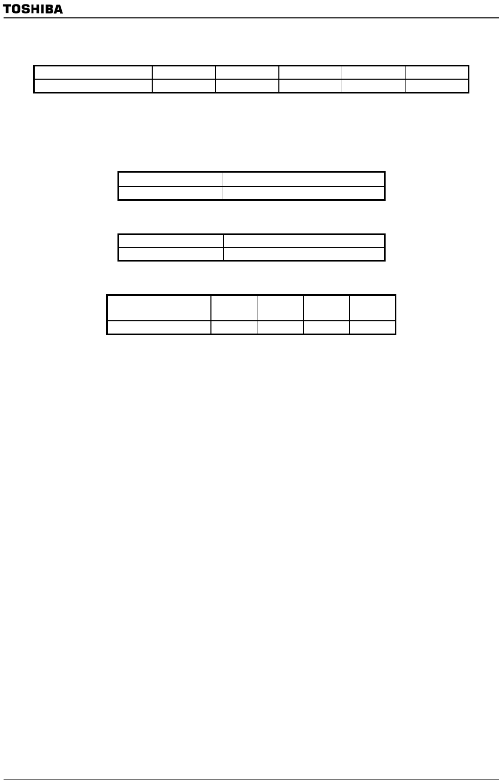
Table 3.4.11 data of measuring frequency
X1-X2 oscillator frequency
(MHz)
6.000 8.000 9.000 10.000
09H 0AH 08H 0BH
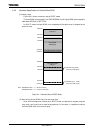
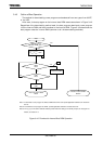
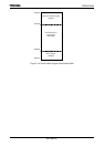
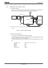
(4) Description of the UART boot program operation
The boot program receives a user program sent from the PC via UART and transfers
it to the internal RAM. If the transfer ends normally, the boot program calculates
SUM and sends the result to the PC before executing the user program. The execution
start address is the first address received. The boot program enables users to perform
customized on-board programming.
When UART is used to download a user program, the maximum allowed program
size is 282 Kbytes (3000H – 49800H). (The extended Intel Hex format is supported.)
a) Operation procedure
1. Connect the serial cable. This must be done before the microcontroller is reset.
2. Set the AM1 and AM0 pins to “1” and reset the microcontroller.
3. The receive data in the 1st byte is matching data (5AH). Upon starting in
BOOT mode, the boot program goes to a state in which it waits for matching
data. When matching data is received, the initial baud rate of the serial
channel is automatically set to 9600 bps.
4. The 2nd byte is used to echo back 5AH to the PC upon completion of the
automatic baud rate setting in the 1st byte. If automatic baud rate setting fails,
the boot program stops operation.
5. The 3rd through 6th bytes are used to send the version management
information of the boot program in ASCII code. The PC should check that the
correct version of the boot program is used.
6. The 7th byte is used to send information on the measured frequency. The PC
should check that the frequency of the resonator is measured correctly.
7. The receive data in the 8th byte is baud rate modification data. The five kinds
of baud rate modification data shown in
Table 3.4.8 are available. Even when