


TMP92CZ26A
92CZ26A-638
5) Data bus occupancy
The TMP92CZ26A includes three controllers (LCD controller, SDRAM controller and
DMAC) that function as bus masters apart from the CPU. Therefore, it is necessary to
estimate the bus occupancy time of each bus master and control each function accordingly
to ensure proper operation of each function. (For details, please refer to the chapter on the
DMA controller.)
In debug mode, in addition to the operations of these bus masters, a steal program that
runs in the background must also be taken into account in programming. When the
program stops at a breakpoint (including step execution), the CPU operation is halted but
the LCD controller, SDRAM controller and DMA controller remain active. At this time, the
steal program also runs in the background. Once the steal program obtains the bus, it
occupies the bus for 80 times of debug transmission clock (LH_SYNCLK) maximum.
Therefore, in some cases, other DMA operations (LCD display, DMAC data transfer,
SDRAM refresh) may not be performed at desired timing.
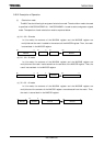
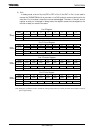
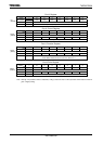
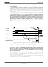
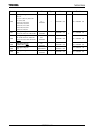
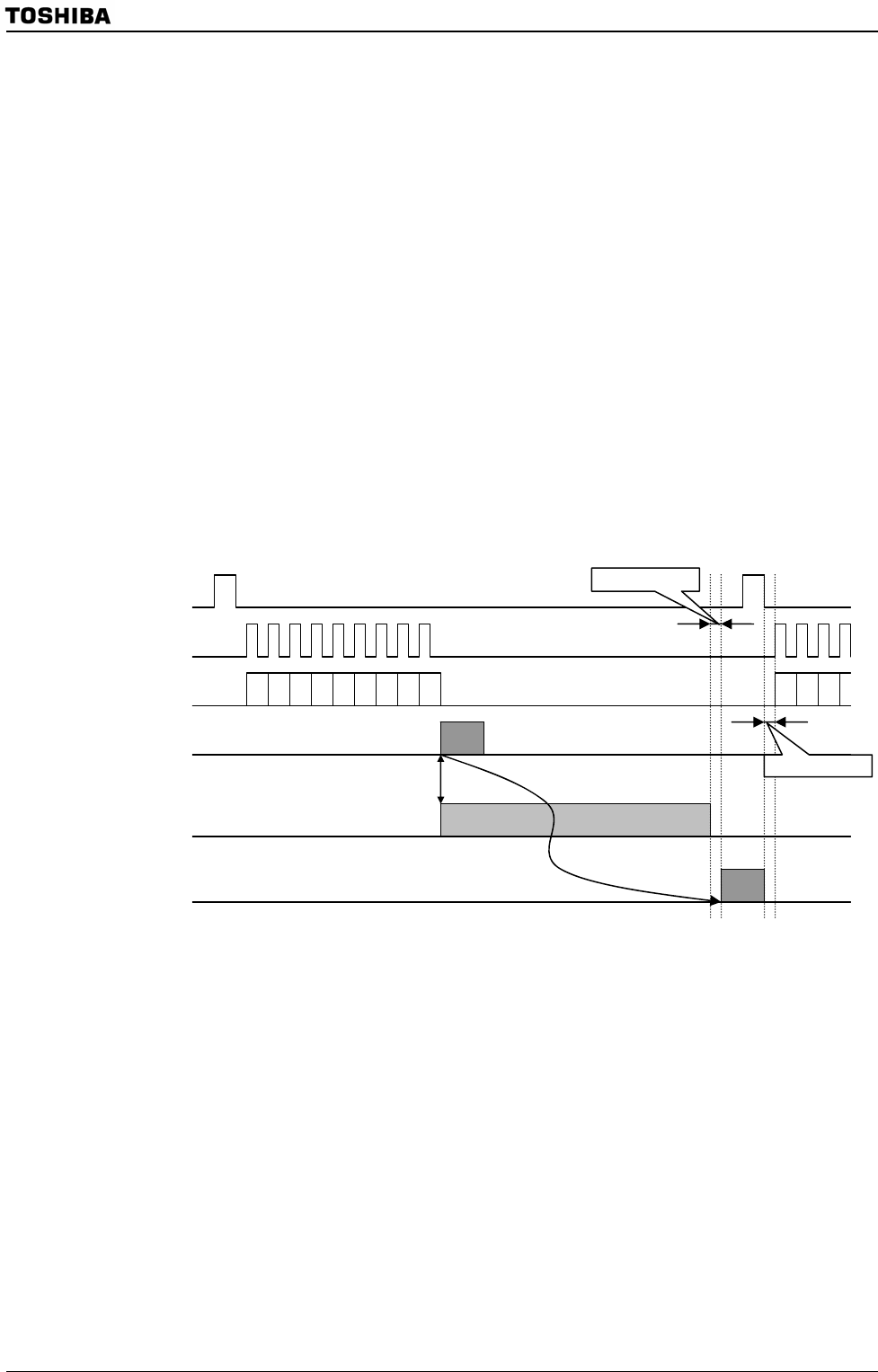
Figure 3.27.1 Example of Data Bus Occupancy Timing in Non-Debug Mode
Figure 3.27.1 shows an example of data bus occupancy timing in non-debug mode,
depicting the LHSYNC signal, LCP0 signal, and LD-bus signal for transferring data from
the LCD controller to the LCD driver, and the LCD DMA operation timing for reading
data from the display RAM.
If HDMA is asserted immediately before the DMA operation for the LCD (LCD DMA
operation 1) is started, this operation must wait until HDMA is finished before it can be
performed (LCD DMA operation 2).
Taking the above into account, it is necessary to ensure that each LCD DMA operation is
finished before the next LCD driver output is started.
LHSYNC
LCP0
LD-bus
LCD DMA operation 1
HDMA operation
(Worst case)
LCD DMA operation 2
Setup time 1
Setup time 2
1
2