


TMP92CZ26A
92CZ26A-616
3.24.2 Operation
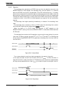
The watchdog timer generates an INTWD interrupt when the detection time set in the
WDMOD<WDTP1:0> has elapsed. The watchdog timer must be cleared “0” in software
before an INTWD interrupt will be generated. If the CPU malfunctions (e.g., if runaway
occurs) due to causes such as noise, but does not execute the instruction used to clear the
binary counter, the binary counter will overflow and an INTWD interrupt will be generated.
The CPU will detect malfunction (runaway) due to the INTWD interrupt and in this case it
is possible to return to the CPU to normal operation by means of an anti-malfunction
program.
The watchdog timer begins operating immediately on release of the watchdog timer
reset.
The watchdog timer is halted in IDLE1 or STOP mode. The watchdog timer counter
continues counting during bus release (when
BUSAK goes low).
When the device is in IDLE2 mode, the operation of WDT depends on the
WDMOD<I2WDT> setting. Ensure that WDMOD<I2WDT> is set before the device enters
IDLE2 mode.
The watchdog timer consists of a 22-stage binary counter which uses the clock (f
IO
) as the
input clock. The binary counter can output 2
15
/ f
IO
, 2
17
/ f
IO
, 2
19
/f
IO
and 2
21
/ f
IO
. Selecting one
of the outputs using WDMOD<WDTP1:0> generates a watchdog timer interrupt when an
overflow occurs.
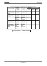
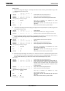
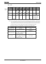
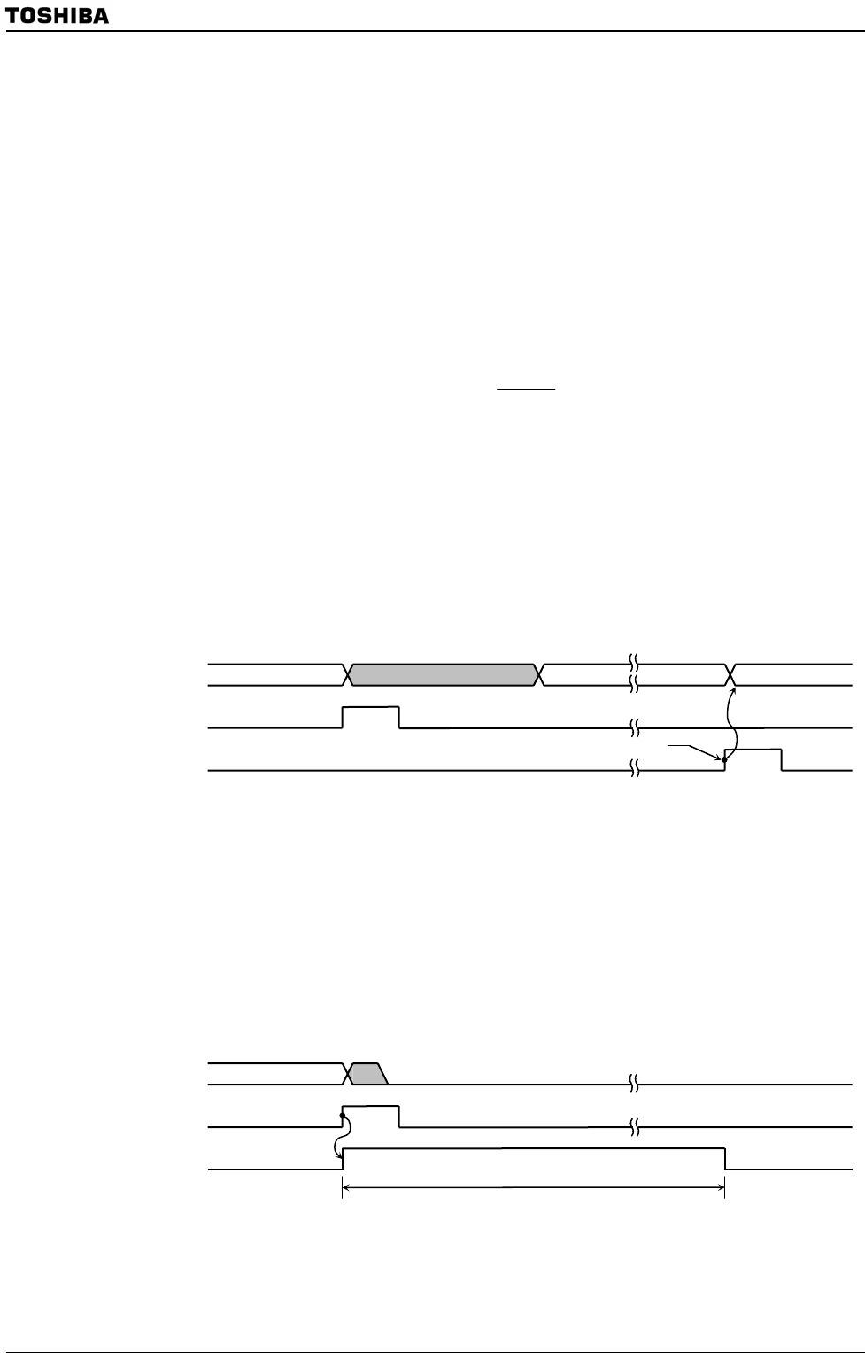
Figure 3.24.2 Normal Mode
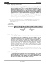
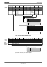
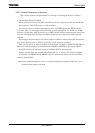
The runaway detection result can also be connected to the reset pin internally.
In this case, the reset time will be 32 clocks (102.4 μs at f
OSCH
= 10 MHz) as shown in
Figure 3.24.3. After a reset, the clock f
IO
is divided f
SYS
by two, where f
SYS
is generated by
dividing the high-speed oscillator clock (f
OSCH
) by sixteen through the clock gear function
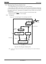
Figure 3.24.3 Reset Mode
Overflow
n 0
WDT counte
r
WDT interru
p
t
WDT clea
r
(Soft ware)
Write clear code
n
WDT counte
r
WDT interru
p
t
32 clocks (102.4
μ
s at f
OSCH
=
10 MHz)
Overflow
Internal reset