


TMP92CZ26A
92CZ26A-538
5. LFR Signal
The LFR (frame) signal is used to control the direction of bias the LCD driver applies
on liquid crystal cells. With small screens in monochrome mode, the polarity of the LFR
signal is normally inverted in synchronization with each screen display. With large
screens or when grayscale or color mode is used, the polarity is inverted at shorter
intervals to adjust the display quality.
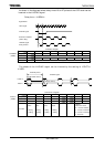
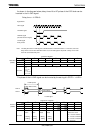
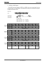
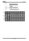
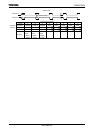
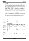
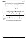
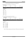
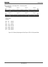
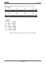
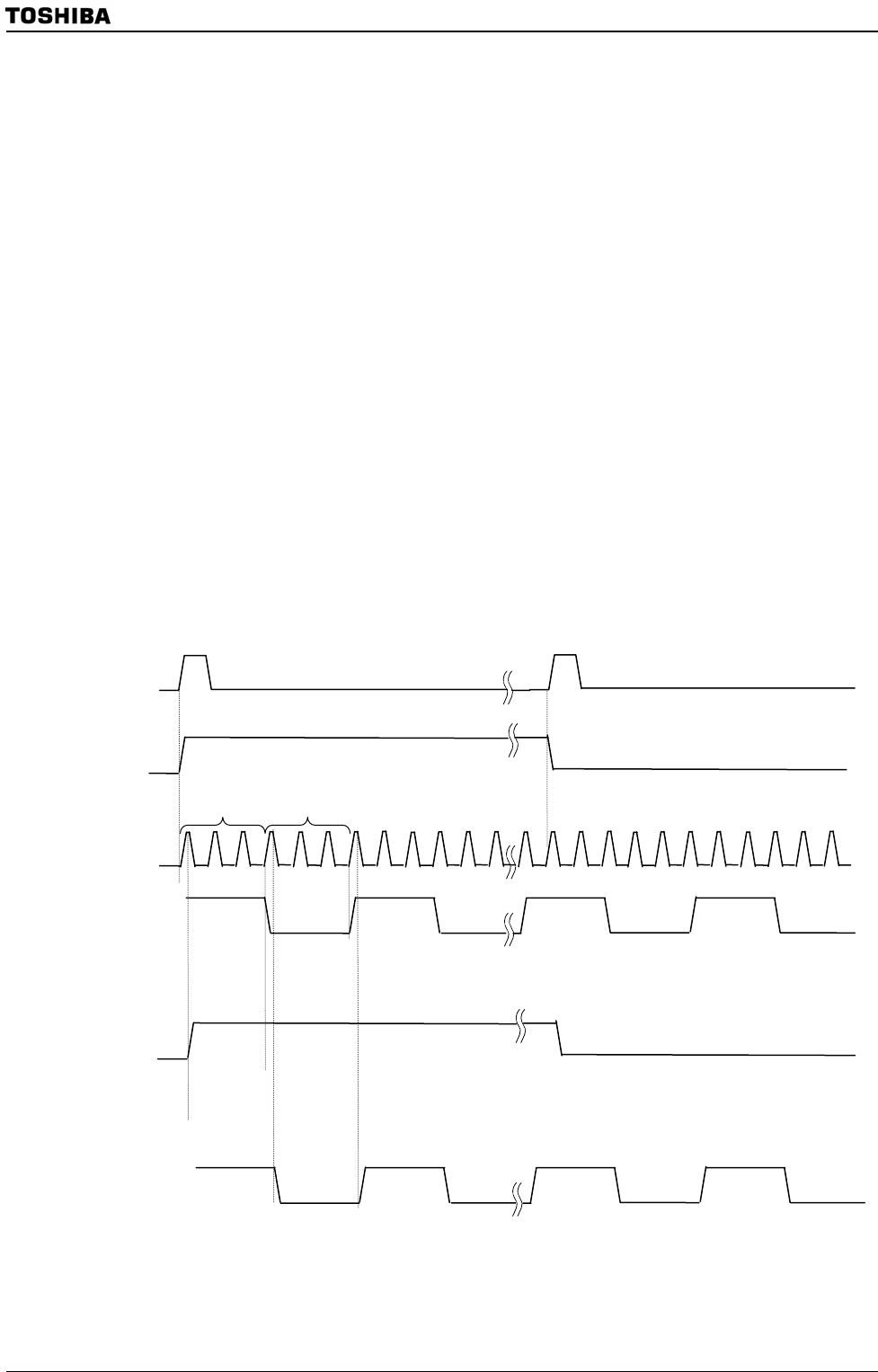
When LCDCTL0<FRMON>=“1” and LCDCTL0<DLS> = “0”, the LFR signal is
inverted at intervals of “LHSYNC x N” (LHSYNC: internal reference signal with 0
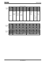
delays). The “N” value is specified in LCDDVM0<FML3:0> and LCDDVM1<FML7:4>.
When <DLS>="0" and <FREDGE>=0, LFR signal synchronous with front edge of
LHSYNC signal, and when <DLS>="0" and <FREDGE>=1, LFR signal synchronous
with rear edge of LHSYNC signal.
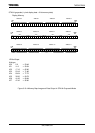
When LCDCTL0<FRMON> is set to “0” to disable the frame divide function, the LFR
signal is inverted in synchronization with the LVSYNC period.
Enabling this function does not affect the waveform and timing of the LVSYNC
signal. (The refresh rate is not changed.)
Note1: The effect of this function varies with the characteristics of the LCD driver and LCD panel to be used.
Note2: LFR signal delaies synchronous with LHSYNC signal.
Generally, setting a prime number (3, 5, 7, 11, 13 and so on) as the “N” value produces better results.
LVSYNC
LFR
<FREDGE>=1
<FRMON> = 0
LFR
<FREDGE>=1
<FRMON>= 1
<FMP7:0> = N
<FML7:0> = any
<DLS> = 0
LFR
<FREDGE>=0
<FRMON> = 0
LHSYNC
LFR
<FREDGE>=0
<FRMON>= 1
<FMP7:0> = N
<FML7:0> = any
<DLS> = 0
N N