


TMP92CZ26A
92CZ26A-318
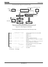
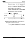
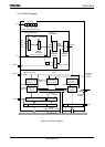
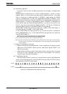
(2) Baud rate generator
The baud rate generator is the circuit which generates transmission/receiving clock
and determines the transfer rate of the serial channels.
The input clock to the baud rate generator, φT0, φT2, φT8 or φT32, is generated by
the 6-bit prescaler which is shared by the timers. One of these input clocks is selected
using the BR0CR<BR0CK1:0> field in the baud rate generator control register.
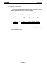
The baud rate generator includes a frequency divider, which divides the frequency
by 1 or N + (16 − K)/16 to 16 values, determining the transfer rate.
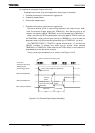
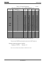
The transfer rate is determined by the settings of BR0CR<BR0ADDE, BR0S3:0>
and BR0ADD<BR0K3:0>.
• In UART mode
When BR0CR<BR0ADDE> = 0
The settings BR0ADD<BR0K3:0> are ignored. The baud rate generator divides
the selected prescaler clock by N, which is set in BR0CK<BR0S3:0>. (N = 1, 2, 3 ...
16)
When BR0CR<BR0ADDE> = 1
The N + (16 − K)/16 division function is enabled. The baud rate generator
divides the selected prescaler clock by N + (16 – K)/16 using the value of N set in
BR0CR<BR0S3:0> (N = 2, 3 ... 15) and the value of K set in BR0ADD<BR0K3:0>
(K = 1, 2, 3 ... 15)
Note: If N = 1 or N = 16, the N + (16 − K)/16 division function is disabled. Clear
BR0CR<BR0ADDE> to 0.
• In I/O interface mode
The N + (16 − K)/16 division function is not available in I/O interface mode. Clear
BR0CR<BR0ADDE> to 0 before dividing by N.
The method for calculating the transfer rate when the baud rate generator is used is
explained below.
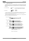
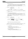
• In UART mode
Baud rate = ÷ 16
• In I/O interface mode
Baud rate = ÷ 2
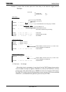
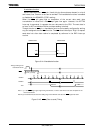
Input clock of baud rate generator
Frequency divider for baud rate generator
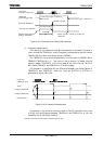
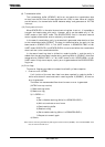
Input clock of baud rate generator
Frequency divider for baud rate generator