


TMP92CZ26A
92CZ26A-614
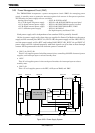
Setting example:
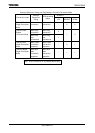
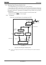
1. Convert the analog input voltage on the AN3 pin and write the result to memory address 2800H using the AD
interrupt(INTAD) processing routine.
Main routine
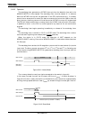
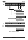
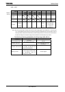
7 6 5 4 3 2 1 0
INTEAD
←
1 1 0 0
−
− − −
Enable INTAD and set it to interrupt level 4.
ADMOD1
←
1 1 0 0 0 0 1 1 Set pin AN3 to be the analog input channel.
ADMOD0
←
X X 0 0 0 0 0 1 Start conversion in channel fixed single conversion mode.
Interrupt routine processing example
WA
←
ADREG3 Read value of ADREG3L and ADREG3H into 16-bits
general-purpose register WA.
WA
←
> > 6 Shift contents read into WA six times to right and zero fill
upper bits.
(2800H)
←
WA Write contents of WA to memory address 2800H.
2. This example repeatedly converts the analog input voltages on the three pins AN0, AN1 and AN2, using channel
scan repeat conversion mode.
INTEAD
←
1 0 0 0
−
− − −
Disable INTAD.
ADMOD1
←
1 1 0 0 0 0 1 0 Set pins AN0 to AN2 to be the analog input channels.
ADMOD0
←
X X 0 0 0 1 1 1 Start conversion in channel scan repeat conversion mode.
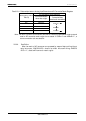
3. Convert the analog input voltage on the AN2 pin as a high-priority AD conversion, and write the result to memory
address 2A00H using the High-priority AD interrupt(INTADHP) processing routine.
Main routine
INTEAD
←
1 1 0 1
−
− − −
Enable INTADHP and set it to interrupt level 6.
ADMOD1
←
1 0 0 0 0 0 0 0 DAC On.
ADMOD3
←
0 0 1 0 0 0 0 0 Set pin AN2 to be the analog input channel.
ADMOD2
←
0 0 0 0 1 0 0 0 Start a high-priority AD conversion by software.
Interrupt routine processing example
WA
←
ADREGSP Read value of ADREGSPL and ADREGSPH into 16-bits
general-purpose register WA.
WA
←
> > 6 Shift contents read into WA six times to right and zero fill
upper bits.
(2A00H)
←
WA Write contents of WA to memory address 2A00H.
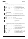
4. Convert the analog input voltage on the AN4 pin as a normal AD conversion of a channel fixed single conversion
mode. And then if its conversion result is greater or equal than the value of (ADCM0REGL/H), write the result to
memory address 2C00H using the AD monitor function interrupt (INTADM) processing routine.
Main routine
INTEAD
←
− − − −
1 0 1 1 Enable INTAD and set it to interrupt level 3.
ADMOD5
←
0 0 0 0 1 0 0 0 Set the analog input channel AN4 for AD monitor function 0.
ADMOD4
←
0 0 1 0 0 0 0 0 Enable the AD monitor function0 and AD monitor function
interrupt 0. Set “a conversion result ≥ AD conversion result
compare criterion register” for generation condition of monitor
function interrupt 0.
ADMOD1
←
1 0 1 0 0 0 0 0 Set pin AN4 to be the analog input channel.
ADMOD0
←
0 0 0 0 1 0 0 0 Start a normal AD conversion by software.
Interrupt routine processing example
WA
←
ADREG4 Read value of ADREG4L and ADREG4H into 16-bits
general-purpose register WA.
WA
←
> > 6 Shift contents read into WA six times to right and zero fill
upper bits.
(2C00H)
←
WA Write contents of WA to memory address 2C00H.
X : Don't care, − : No change