


TMP92CZ26A
92CZ26A-218
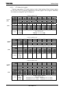
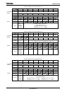
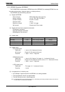
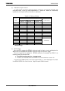
3.9.3 Setting example
This is in case of using like following condition.
No. Used as Memory Setting MMU-area Logical
address
Physical
address
(a) Main
Routine
COMMON-Z C00000H to
FFFFFFH
(b) Character-
ROM
NOR-Flash
(16MB, 1pcs)
CSZA ,
32bit,
1wait
Bank0 in
LOCAL-Z
800000H to
BFFFFFH
000000H to
3FFFFFH
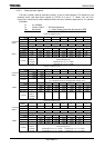
(c) Sub
Routine
Bank0 in
LOCAL-Y
000000H to
1FFFFFH
(d) LCD
Display-RAM
SRAM
(16MB, 1pcs)
1CS ,
16bit,
0wait
Bank1 in
LOCAL-Y
400000H to
5FFFFFH
200000H to
3FFFFFH
(e) Stack-
RAM
Internal-RAM
(288KB)
----
(32bit,
2-1-1-1clk)
Bank2 in
LOCAL-Y
002000H to
049FFFH
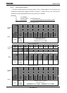
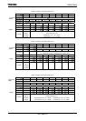
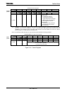
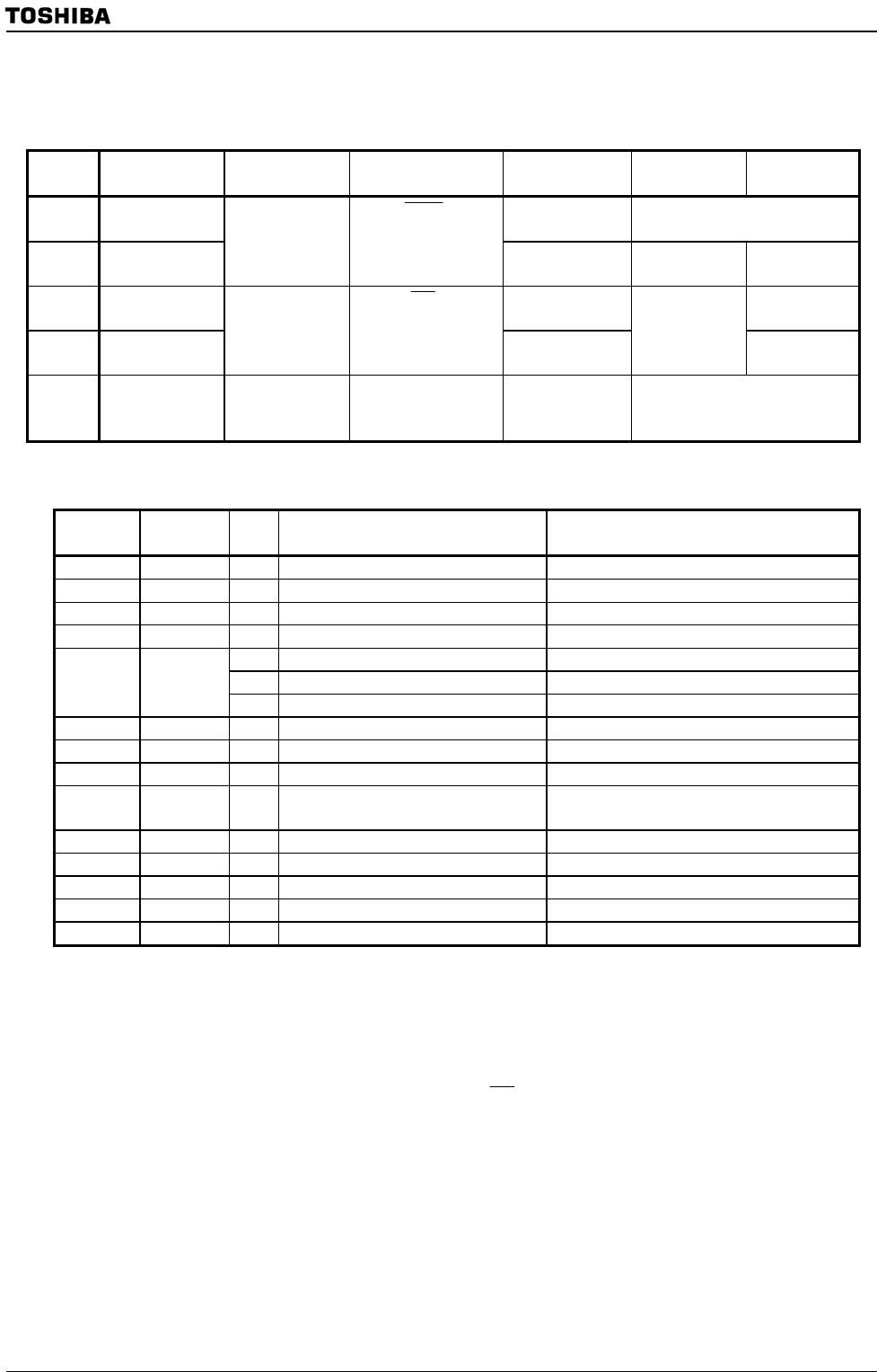
(a) Main routine (COMMON-Z)
Logical
Address
Physical
Address
No Instruction Comment
1 org C00000H ;
C00000H <-(Same) 2 ldw (mamr2),80FFH ; CS2 800000-ffffff/8MB
C000xxH <- 3 ldw (b2csl), C222H ; CS2 32bit ROM, 1wait
4 ldw (mamr1),40FFH ; CS1 400000-7fffff/4MB
5 ldw (b1csl), 8111H ; CS1 16bit RAM, 0wait
5.1 ldw (localpz),8000H ; Enable LOCAL-Z Bank for program
5.2 ldw (localrz),8000H ; Enable LOCAL-Z Bank for read-data
6 ld (p8fc), 02H ;
7 ld (p8fc2), 04H ;
9 ld xsp,48000H ; Stack Pointer = 48000H
10 ldw (localpy),8000H ; Bank0 in LOCAL-Y is set as Program bank
for sub routine
11 : ;
C000yyH <- 12 call 400000H ; Call Sub routine
13 : ;
14 : ;
15 : ;
From No.2 to No.8 instructions are setting of Ports and Memory controller.
No.9 is a setting for stack pointer. It is assigned to internal-RAM.
No.10 is a setting to execute for No.12’s instruction.
No.12 is an instruction to call sub routine. When CPU outputs 400000H address, MMU will convert and output 000000H
physical address to external address bus: A23 to A0. And
1CS
for SRAM will be asserted because of logical address is
in an area for CS1 at the same time. By these instructions, CPU cans brunch to sub-routine.
(Note: This example is based on sub routine program is already written on SRAM.)