


TMP92CZ26A
92CZ26A-524
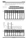
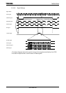
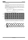
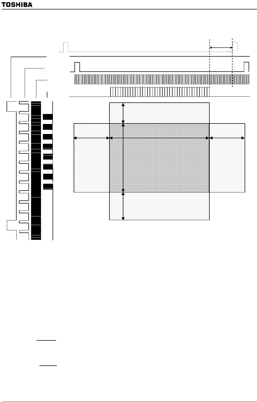
• Insertion of dummy clocks
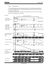
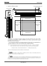
The above is a conceptual diagram showing the data (LD23-0), shift clock (LCP0),
horizontal synchronization signal (LHSYNC), and vertical synchronization signal
(LVSYNC) on the LCD panel.
The front porch and back porch as shown above should be taken into consideration in
setting LCDHSP<LH15:0> and LCDVSP<LV9:0> explained earlier.
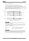
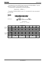
Note 1: The horizontal back porch must be set so that “data transfer” plus “LCP0 × 2 clocks” are completed
within one period of the reference clock LHSYNC (with 0 delay), as defined by the following equation:
Delay time (LLOAD) + number of data transfer times + 2 < LHSYNC (LCP0 pulse count)
Note 2: The vertical back porch must have a minimum of one dummy clock.
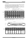
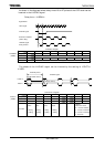
(*) TFT driver
The recommended number of dummy clocks is specified by each TFT driver (or LCD module). Refer to the
specifications of the TFT driver (LCD module) to be used.
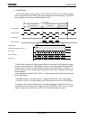
(*) STN driver
For an STN driver, the refresh rate can be set accurately by adjusting the value of the horizontal back porch. If the
desired refresh rate cannot be obtained by the horizontal back porch, it can be further adjusted by the vertical back porch.
For details, refer to the setting example to be described later in this section.
LD23-0
LCP0
LHSYNC
(with delay)
LVSYNC
Vertical Front Porch
Horizontal Front
Porch
Horizontal back
Porch
Vertical back Porch
Reference LHSYNC
(Delay=0)
Note: At least two LCP0 pulses
must be inserted.