


TMP92CZ26A
92CZ26A-601
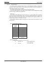
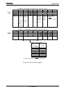
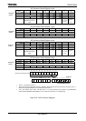
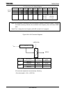
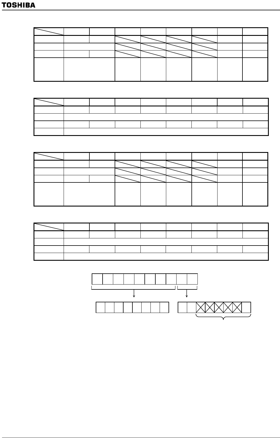
AD Conversion Result Register 2 Low
7 6 5 4 3 2 1 0
bit Symbol ADR21 ADR20 OVR2 ADR2RF
Read/Write R R R
After reset 0 0 0 0
Function Store Lower 2 bits of
AN2 AD conversion
result
Overrun flag
0:No generate
1: Generate
AD conversion
result store
flag
1: Stored
AD Conversion Result Register 1 High
7 6 5 4 3 2 1 0
bit Symbol ADR29 ADR28 ADR27 ADR26 ADR25 ADR24 ADR23 ADR22
Read/Write R
After reset 0 0 0 0 0 0 0 0
Function Store Upper 8 bits of AN2 AD conversion result
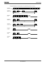
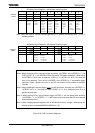
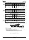
AD Conversion Result Register 3 Low
7 6 5 4 3 2 1 0
bit Symbol ADR31 ADR30 OVR3 ADR3RF
Read/Write R R R
After reset 0 0 0 0
Function Store Lower 2 bits of
AN3 AD conversion
result
Overrun flag
0:No generate
1: Generate
AD conversion
result store
flag
1: Stored
AD Conversion Result Register 3 High
7 6 5 4 3 2 1 0
bit Symbol ADR39 ADR38 ADR37 ADR36 ADR35 ADR34 ADR33 ADR32
Read/Write R
After reset 0 0 0 0 0 0 0 0
Function Store Upper 8 bits of AN3 AD conversion result
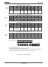
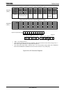
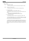
9 8 76543210
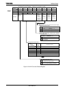
Channel X conversion result
7 6 543210 76543 2 1 0
Figure 3.23.7 AD Conversion Registers
A
DREG2L
(12A4H)
ADREG2H
(12A5H)
A
DREG3L
(12A6H)
A
DREG3H
(12A7H)
A
DREGxH ADREGxL
• Bits 5 ∼ 2 are always read as “0”.
• Bit 0 is the AD conversion result store flag <ADRxRF>. When AD conversion result is stored, the flag is set to “1”.
When Lower register (ADRECxL) is read, this bit is cleared to “0”.
• Bit 1 is the Overrun flag <OVRx>. This bit is set to “1” if a next conversion result is written to the ADREGxH/L
before both the ADREGxH and ADREGxL are read. This bit is cleared to “0” by reading Flag.