


TMP92CZ26A
92CZ26A-428
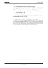
3. Data packet is received.
Device request of 8 bytes from SIE in UDC is transferred to below
request register.
• bmRequestType register
• bmRequest register
• wValue register
• wIndex register
• wLength register
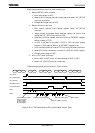
4. After last data was transferred, and compare counted CRC with
transferred CRC. If it doesn’t conform, it sets STATUS to RX_ERR and
state return to IDLE. At this point it doesn’t return ACK, and host retry.
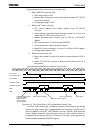
5. If CRC compare with toggle and it finish normally, ACK handshake is
returned to host. Bellow is process in UDC.
• Receiving device request is judged whether software control or
hardware control, if request need control in software, request is
informed receiving to external by asserting INT_SETUP interrupt.
If using hardware, INT_SETUP interrupt is not asserted.
• According to stage control flow, prepare for next stage.
• Set STATUS to DATAIN.
• Set toggle bit to “1”.
Setup stage finishes by above.
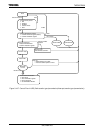
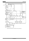
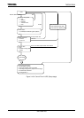
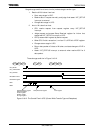
This flow is
Figure 3.16.6.
8-byte data that is transferred by this SETUP stage is device request.
CPU must process correspond it device request.
UDC detects following contents only from data of 8 bytes, and it manages
stage in hardware.
• There is data stage or not
• Data stage direction
It judges control read transfer type, control write transfer type, control
write transfer type (not data phase) by them.