TMP92CZ26A
92CZ26A-519
3.19.3.4 Reference Clock LCP0
LCP0 is used as the reference clock for all the signals in the LCDC.
This section explains how to set the frequency (period) of the LCP0 signal.
The LCP0 clock speed (LD bus transfer speed) is determined by selecting TFT or STN
and setting LCDMODE0<SCPW1:0> and LCDMODE1<SWPW2>. The clock speed should
be selected to meet the characteristics of the LCD driver to be used.
The LCP0 period can be selected from four types: f
SYS
/2, f
SYS
/4, f
SYS
/8, f
SYS
/16, f
SYS
/24 and
f
SYS
/48.
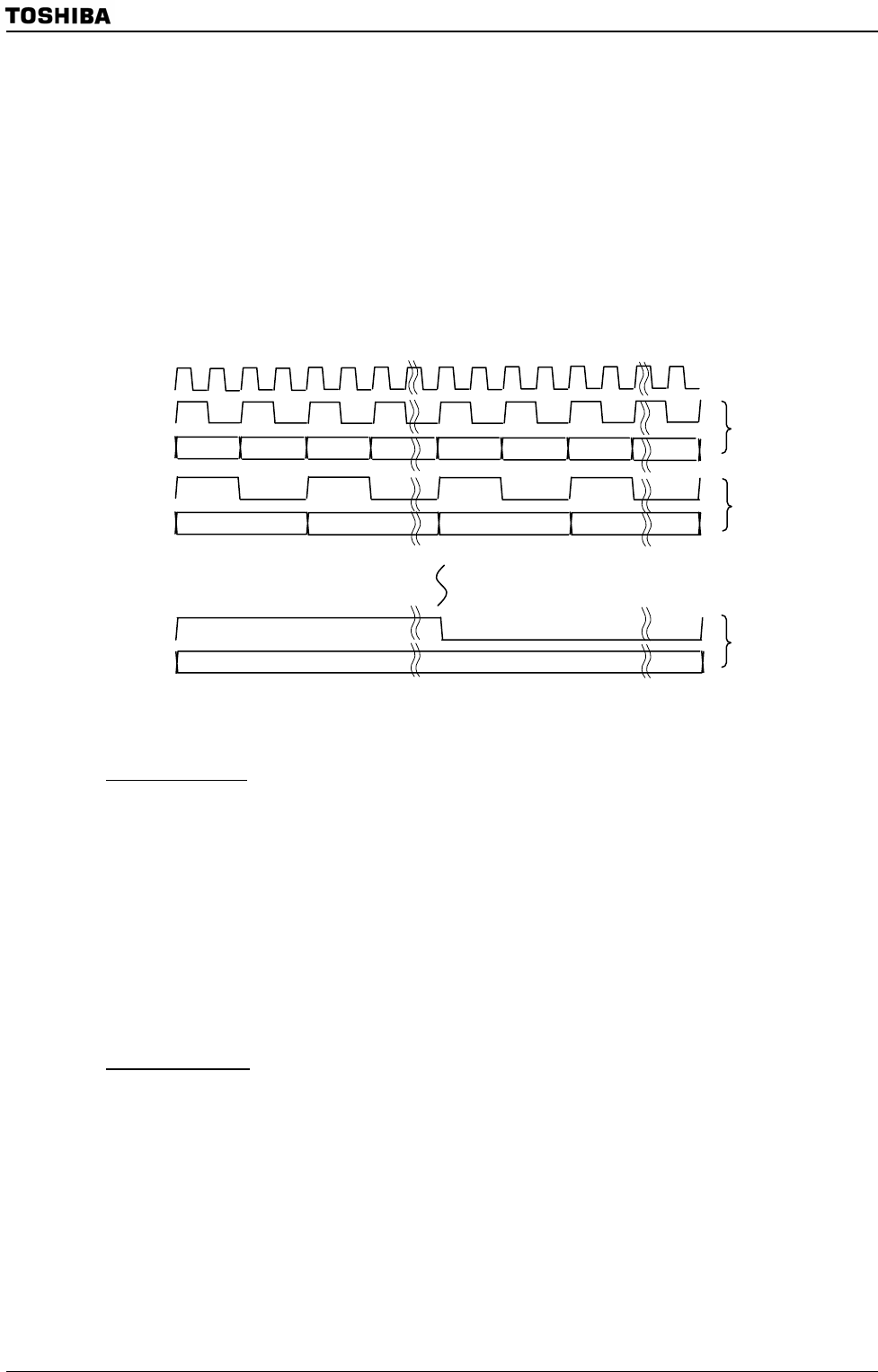
Figure 3.19.1 LCP Frequency Selection
Minimum speed
The LCP0 period needs to be short enough to prevent the next line signal from
overlapping the current line signal.
The transfer speed of display data must be set to suit the refresh rate; otherwise data
cannot be transferred properly. Set the data transfer speed so that each transfer
completes within the LHSYNC period.
Maximum speed
If the LCP0 period is too short, the data to be transferred to the LCD driver cannot be
prepared in time, causing wrong data to be transferred. The maximum transfer speed
is limited by the operation mode and display RAM type (bus width, wait condition, and
so on). If the data rotation function is used, the transfer speed must be slower.
STN monochrome/grayscale : Segment size / 8 × LCP0 [s: period] < LHSYNC
[s: period] STN color
STN color : Segment size × 3 / 8 LCP0 [s: period] < LHSYNC
[s: period]
TFT : Segment size × LCP0 [s: period] < LHSYNC [s: period]
fsys / 4
LCP0
fsys /48
LD23-LD0
LCP0
Internal signal (fsys)
fsys / 2
LCP0
LD23-LD0
LD23-LD0


