


TMP92CZ26A
92CZ26A-623
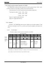
• Exiting the Power Cut Mode
The Power Cut Mode can be exited by external or internal interruption. (It inhibits to exit
the Power Cut Mode by reset when DVCC1A is cut off. Reset must be asserted after supplying
power to DVCC1A and waiting for its voltage to fully stabilize.) The interrupts that can be
used to exit the Power Cut Mode are RTC interrupt, INT0 to INT7 (TSI interrupt) and
INTKEY interrupt.
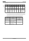
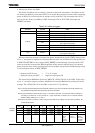
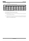
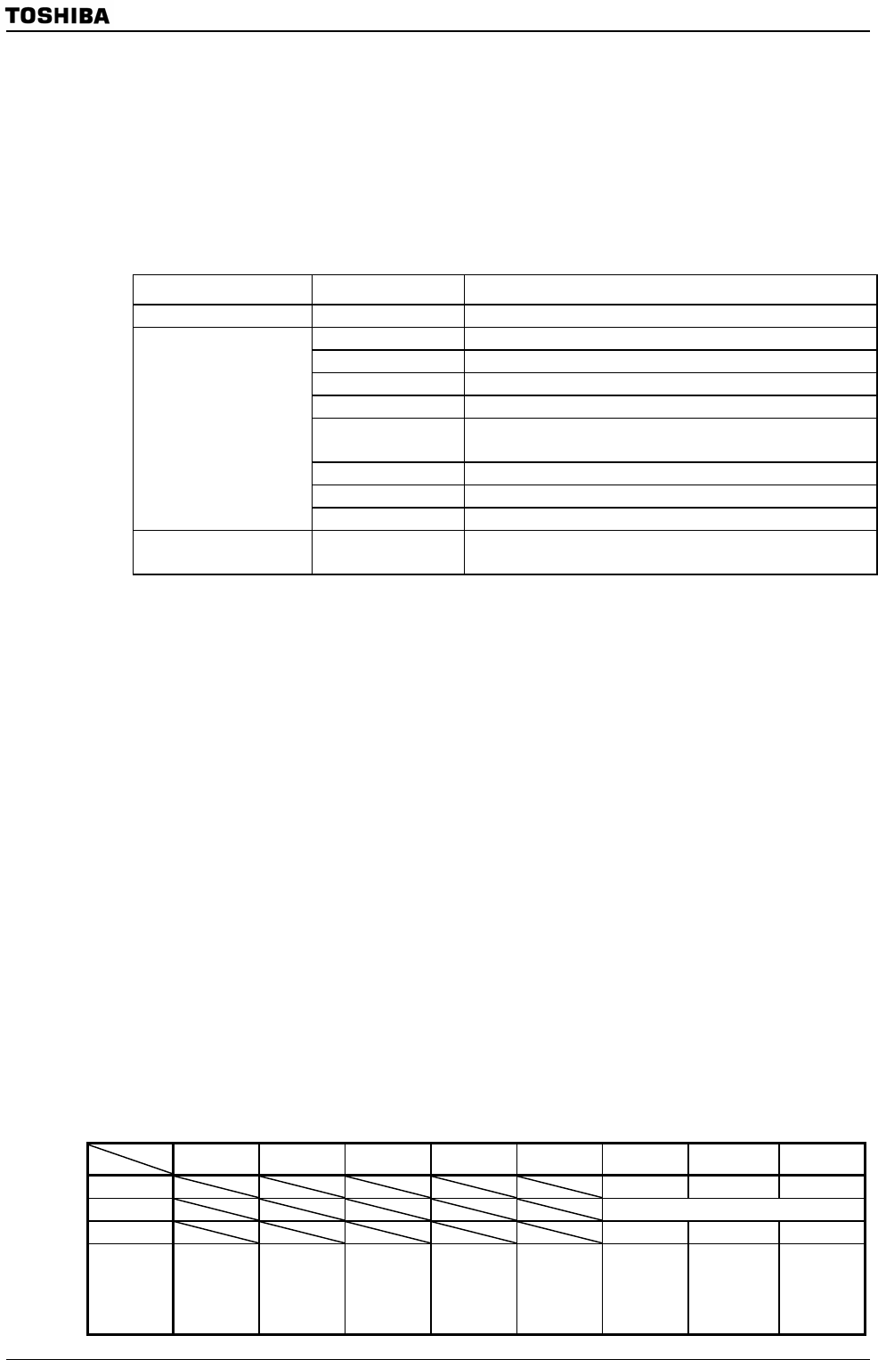
Table 3.25.1 Wake-up triggers
Source Symbol Note
RTC INTRTC
INT0 Only support "Rising Edge"
INT1 Only support "Rising Edge"
INT2 Only support "Rising Edge"
INT3 Only support "Rising Edge"
INT4
When TSI, need to disable de-bounce circuit
Only support "Rising Edge"
INT5 Only support "Rising Edge"
INT6 Only support "Rising Edge"
External
INT7 Only support "Rising Edge"
Key INTKEY
KI0~KI8
Only support "Falling Edge"
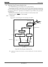
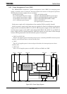
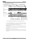
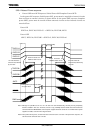
When an interrupt request is accepted, the power management signals (PWE) changes from
“0” to “1” and power is supplied to each block that has been cut off. After the warm-up time set
in PMCCTL<WUTM1:0> has elapsed, HOT_RESET is automatically released and the CPU
starts up from the internal boot ROM regardless of the external AM pin state. All external
ports retain the state before entering the Power Cut Mode except for the PnDR setting which
is released upon release of HOT_RESET.
* Output pin Hi-Z state → “1” or “0” output
* Input pin input gate OFF → Input pin input gate ON
The internal boot ROM first checks the PMCCTL <PCM_ON> bit in the PMC. If this bit is
set to “1”, execution jumps to address 46000H in the internal RAM before making all initial
settings. The <PCM_ON> bit in the PMC is cleared to “0” by software.
Note 1: The interrupt that released the Power Cut Mode, whichever it is, does not activate any interrupt operation. Nor
is it possible to identify which interrupt released the Power Cut Mode.
Note 2: Once the PMCCTL<PCM_ON> bit is set to “1”, it remains in this state. To re-enter the Power Cut Mode, it is
necessary to set this bit to “0” once and then to “1” again. At this time, a minimum of 31 us must be inserted
between setting <PCM_ON> to “0” and “1”.
Note 3: Since the Power Cut Mode is exited using the boot ROM, some settings must be made by software. Be
careful about this point.
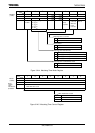
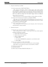
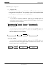
7 6 5 4 3 2 1 0
Bit symbol CSDIS ROMLESS VACE BROMCR
(016CH)
Read/Write R/W
After reset 1 0 1
Function
NAND Flash
area CS
output
0: Enable
1: Disable
Boot ROM
0: Used
1: Not used
Vector
address
conversion
0: Disable
1: Enable