


TMP92CZ26A
92CZ26A-492
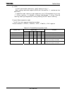
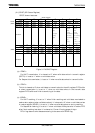
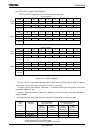
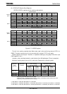
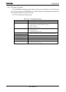
(4) SPICR (SPI CRC Register)
CRC result of Transmit/Receive data is set to SPICR register.
SPICR Register
7 6 5 4 3 2 1 0
bit Symbol
CRCD7 CRCD6 CRCD5 CRCD4 CRCD3 CRCD2 CRCD1 CRCD0
Read/Write
R
After Reset
0 0 0 0 0 0 0 0
Function
CRC result register [7:0]
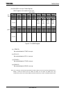
15 14 13 12 11 10 9 8
bit Symbol
CRCD15
CRCD14 CRCD13 CRCD12 CRCD11 CRCD10 CRCD9 CRCD8
Read/Write
R
After Reset
0 0 0 0 0 0 0 0
Function
CRC result register [15:8]
Figure 3.17.11 SPICR Register
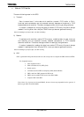
(a) <CRCD15:0>
The result which is calculated according to the setting; SPICT<CRC16_7_b>,
<CRCRX_TX_B> and <CRCRESET_B>, are loaded to this register.
In case CRC16, all bits are valid.
In case CRC7, lower 7 bits are valid.
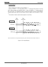
The flow will be showed to calculate CRC16 of received data for instance by flowchart.
Firstly, initialize CRC calculation register by writing <CRCRESET_B>= “1” after
setting <CRC16_7_b>= “1”, <CRCRX_TX_B>=”0”, <CRCRESET_B>= “0”.
Next, finish transmitting all bits to calculate CRC by writing data in SPITD register.
Please sense SPIST<TEND> to confirm whether receiving is finished.
If read SPICR register after finishing, CRC16 of received data can be read.
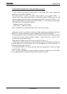
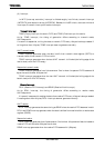
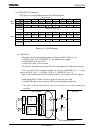
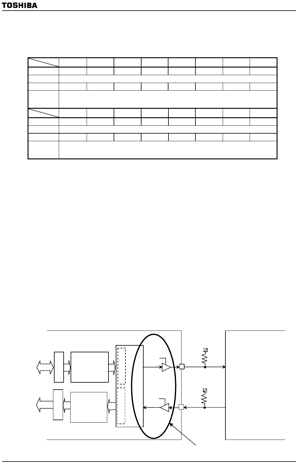
Note: CRC is generated in I/O point. Please take care soft ware process to compare the CRC when
used FIFO.
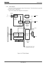
SPICR
(826H)
(827H)
SPITD
Transmitt,Receive ontroller
SPDO
16bit
SPIRD
SPDI
DI
DO
100KΩ
100KΩ
Internal data bus
TX FIFO
8×32
RX FIFO
8×32
16bit
RX shift register
TX shft register
TMP92CZ26A
SPI slave
CRC generation point