


TMP92CZ26A
92CZ26A-352
b. Clock synchronization
In the I
2
C bus mode, in order to wired-AND a bus, a master device which pulls down
a clock line to low-level, in the first place, invalidate a clock pulse of another master
device which generates a high-level clock pulse. The master device with a high-level
clock pulse needs to detect the situation and implement the following procedure.
The TMP92CZ26A has a clock synchronization function for normal data transfer even
when more than one master exists on the bus.
The example explains the clock synchronization procedures when two masters
simultaneously exist on a bus.
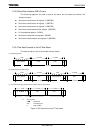
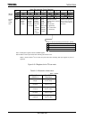
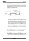
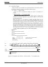
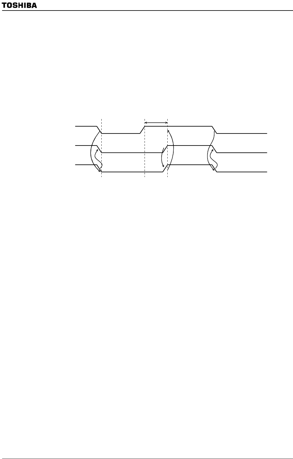
Figure 3.15.9 Clock synchronization
As Master A pulls down the internal SCL output to the Low level at point “a”,
the SCL line of the bus becomes the Low-level. After detecting this situation,
Master B resets a counter of High-level width of an own clock pulse and sets the
internal SCL output to the Low-level.
Master A finishes counting Low-level width of an own clock pulse at point “b” and
sets the internal SCL output to the High-level. Since Master B holds the SCL line
of the bus at the Low-level, Master A wait for counting high-level width of an own
clock pulse. After Master B finishes counting low-level width of an own clock
pulse at point “c” and Master A detects the SCL line of the bus at the High-level,
and starts counting High-level of an own clock pulse. The clock pulse on the bus is
determined by the master device with the shortest High-level width and the
master device with the longest Low-level width from among those master devices
connected to the bus.
(4) Slave address and address recognition mode specification
When the TMP92CZ26A is used as a slave device, set the slave address <SA6:0> and
<ALS> to the I2CAR. Clear the <ALS> to “0” for the address recognition mode.
(5) Master/Slave selection
Set the SBICR2<MST> to “1” for operating the TMP92CZ26A as a master device.
Clear the SBICR2<MST> to “0” for operation as a slave device. The <MST> is cleared
to “0” by the hardware after a stop condition on the bus is detected or arbitration is
lost.
Internal SCL output
(Master A)
Internal SCL output
(Master B)
SCL pin
Reset a counting o
f
high-level width of a
clock pulse
Wait counting high-level
width of a clock pulse
Start countin
g
hi
g
h-level width of a clock
p
ulse
a b c