


TMP92CZ26A
92CZ26A-82
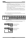
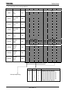
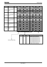
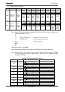
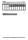
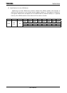
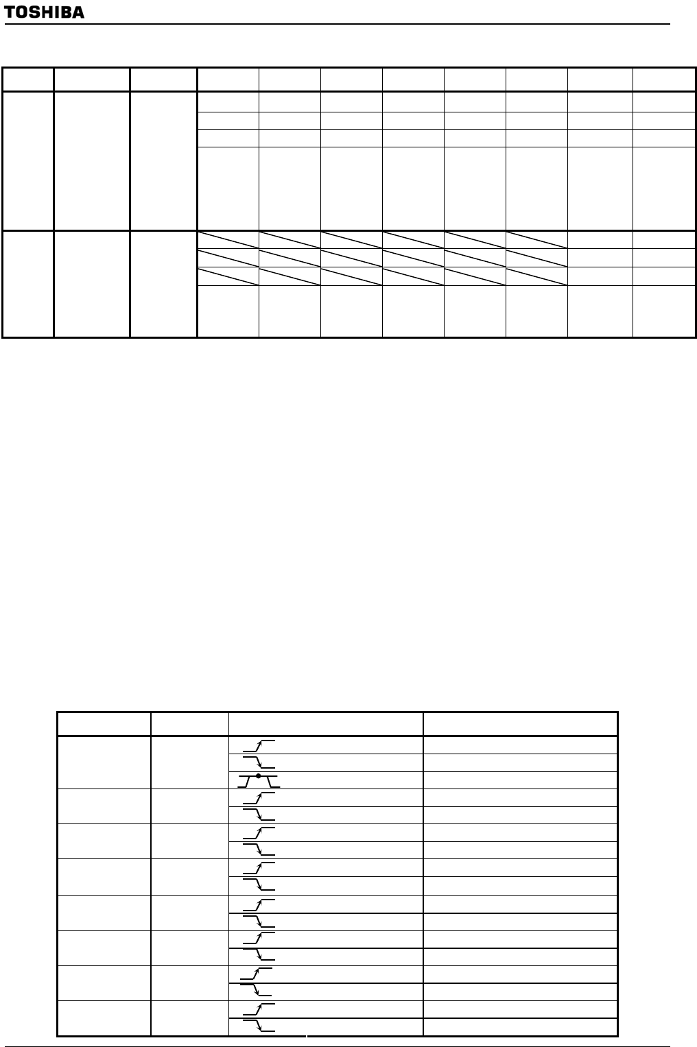
(2) External interrupt control
Symbol Name Address 7 6 5 4 3 2 1 0
I5EDGE I4EDGE I3EDGE I2EDGE I1EDGE I0EDGE I0LE
−
W W W W W W R/W R/W
0 0 0 0 0 0 0 0
IIMC0
Interrupt
input mode
control 0
F6H
(Prohibit
RMW)
INT5EDGE
0: Rising
1: Falling
INT4EDGE
0: Rising
1: Falling
INT3EDGE
0: Rising
1: Falling
INT2EDGE
0: Rising
1: Falling
INT1EDGE
0: Rising
1: Falling
INT0EDGE
0: Rising
1: Falling
INT0
0: Edge
mode
1: Level
mode
Always
write “0”
.
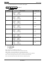
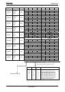
I7EDGE I6EDGE
W W
0 0
IIMC1
Interrupt
input mode
control 0
FAH
(Prohibit
RMW)
INT7EDGE
0: Rising
1: Falling
INT6EDGE
0: Rising
1: Falling
Note 1: Disable INT0 request before changing INT0 pin mode from level sense to edge sense.
(change <I0LE>from “1” to “0”)
DI
LD (IIMC0), XXXXXX0-B ; Switches from level to edge.
LD (INTCLR), 0AH ; Clears interrupt request flag.
NOP ; Wait EI execution
NOP
NOP
EI
Note 2: X: Don’t care, –: No change
Note 3: See electrical characteristics in section 4 for external interrupt input pulse width.
Note 4: In port setting, if 16 bit timer input is selected and capture control is executed, INT6 and
INT7 don’t depend on IIMC1 register setting. INT6 and INT7 operate by setting
TBnMOD<TBnCPM1:0>.
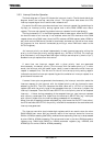
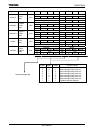
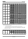
Settings of External Interrupt Pin Function
Interrupt Pin Name Mode Setting Method
Rising edge <I0LE> = 0,<I0EDGE> = 0
Falling edge <I0LE> = 0, <I0EDGE> = 1
INT0 PC0
High level <I0LE> = 1
Rising edge <I1EDGE> = 0
INT1 PC1
Falling edge <I1EDGE> = 0
Rising edge <I2EDGE> = 0
INT2 PC2
Falling edge <I2EDGE> = 1
Rising edge <I3EDGE> = 0
INT3 PC3
Falling edge <I3EDGE> = 1
Rising edge <I4EDGE> = 0
INT4 P96
Falling edge <I4EDGE> = 1
Rising edge <I5EDGE> = 0
INT5 PP3
Falling edge <I5EDGE> = 1
Rising edge <I6EDGE> = 0
INT6 PP4
Falling edge <I6EDGE> = 1
Rising edge <I7EDGE> = 0
INT7 PP5
Falling edge <I7EDGE> = 1