


TMP92CZ26A
92CZ26A-560
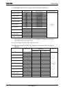
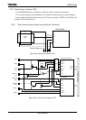
3. Setting Method
The <LDC2:0> bits in the LCDMODE1 register are used to set the display data
rotation function.
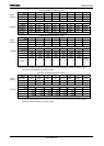
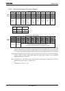
LCDMODE1 Register
7 6 5 4 3 2 1 0
bit Symbol LDC2 LDC1
LDC0 LDINV AUTOINV INTMODE FREDGE SCPW2
Read/Write R/W R/W R/W R/W R/W R/W W W
After reset 0 0 0 0 0 0 0 0
Function
Data rotation function
(Supported for 64K-color: 16 bps
only)
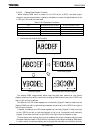
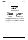
000: Normal 100: 90-degree
001: Horizontal flip 101: Reserved
010: Vertical flip 110: Reserved
011: Horizontal and vertical flip
111: Reserved
LD bus
inversion
0: Normal
1: Invert
Auto bus
inversion
0: Disable
1: Enable
(Valid for
TFT only)
Interrupt
selection
0:LLOAD
1:LVSYNC
LFR edge
0: LHSYNC
Front Edge
1:LHSYNC
Rear Edge
LD bus
Trance
Speed
0: normal
1: 1/3
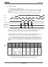
Note: The <LDC2:0> setting must not be changed while the LCDC is operating. Be sure to set
LCDCTL0<START> to “0” to stop the LCDC operation before changing <LDC2:0>.
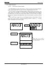
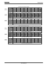
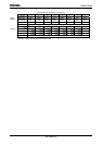
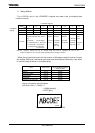
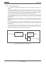
When the horizontal and vertical flip function or 90-degree rotation function is used,
the display RAM start address of main/sub area should be set differently from when
in normal mode, as shown in the table below.
Mode Setting Point Display RAM Start Address
Setting Example
Normal Point A 00000h
90-degree rotation Point B 257FEh
Horizontal flip Point A 00000h
Vertical flip Point B 257FEh
Horizontal and vertical flip Point B 257FEh
How to calculate the point B address:
(320×240×16/8)- 2 = 153600 - 2
= 153598 [decimal]
= 257FE [hex]
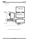
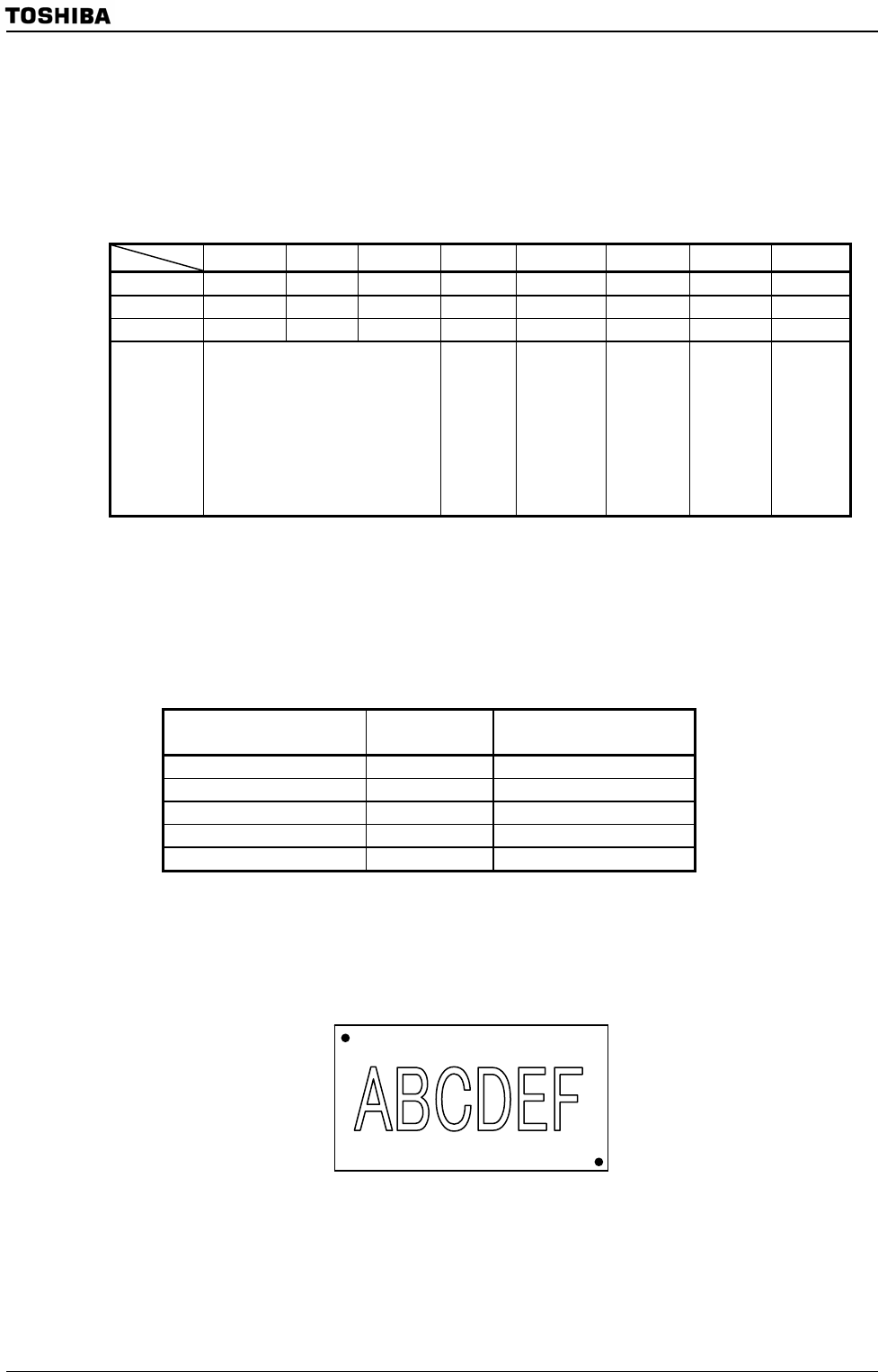
Display RAM Image (QVGA 320 × 240)
Point A
Point B
LCDMODE1
(0281H)