


TMP92CZ26A
92CZ26A-337
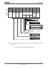
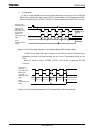
Main routine
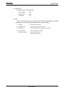
7 6543210
P9CR
←
X XXXX
−
0
−
Set P91 to function as the RXD0 pin.
P9FC
← − −
XXX
−
X
−
SC0MOD0
← − −
1
−
1 0 0 1 Enable receiving in 8-bit UART mode.
SC0CR
←
−
01
− − − − −
Add odd parity.
BR0CR
←
0 0 0 1 1 0 0 0 Set the transfer rate to 9600 bps.
INTES0
←
X 1 0 0 X 0 0 0 Enable the INTTX0 interrupt and set it to interrupt
level 4.
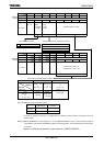
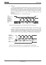
Interrupt routine
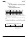
A
CC
←
SC0CR AND 00011100
if A
CC
≠ 0 then ERROR
Check for errors
A
CC
←
SC0BUF Read the received data
X: Don't care, −: No change
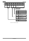
(4) Mode 3 (9-Bit UART Mode)
9-Bit UART Mode is selected by setting SC0MOD0<SM1:0> to 11. In this mode
parity bit cannot be added.
In the case of transmission the MSB (9th bit) is written to SC0MOD0<TB8>. In the
case of receiving it is stored in SC0CR<RB8>. When the buffer is written and read, the
MSB is read or written first, before the rest of the SC0BUF data.
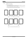
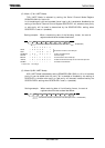
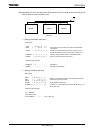
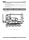
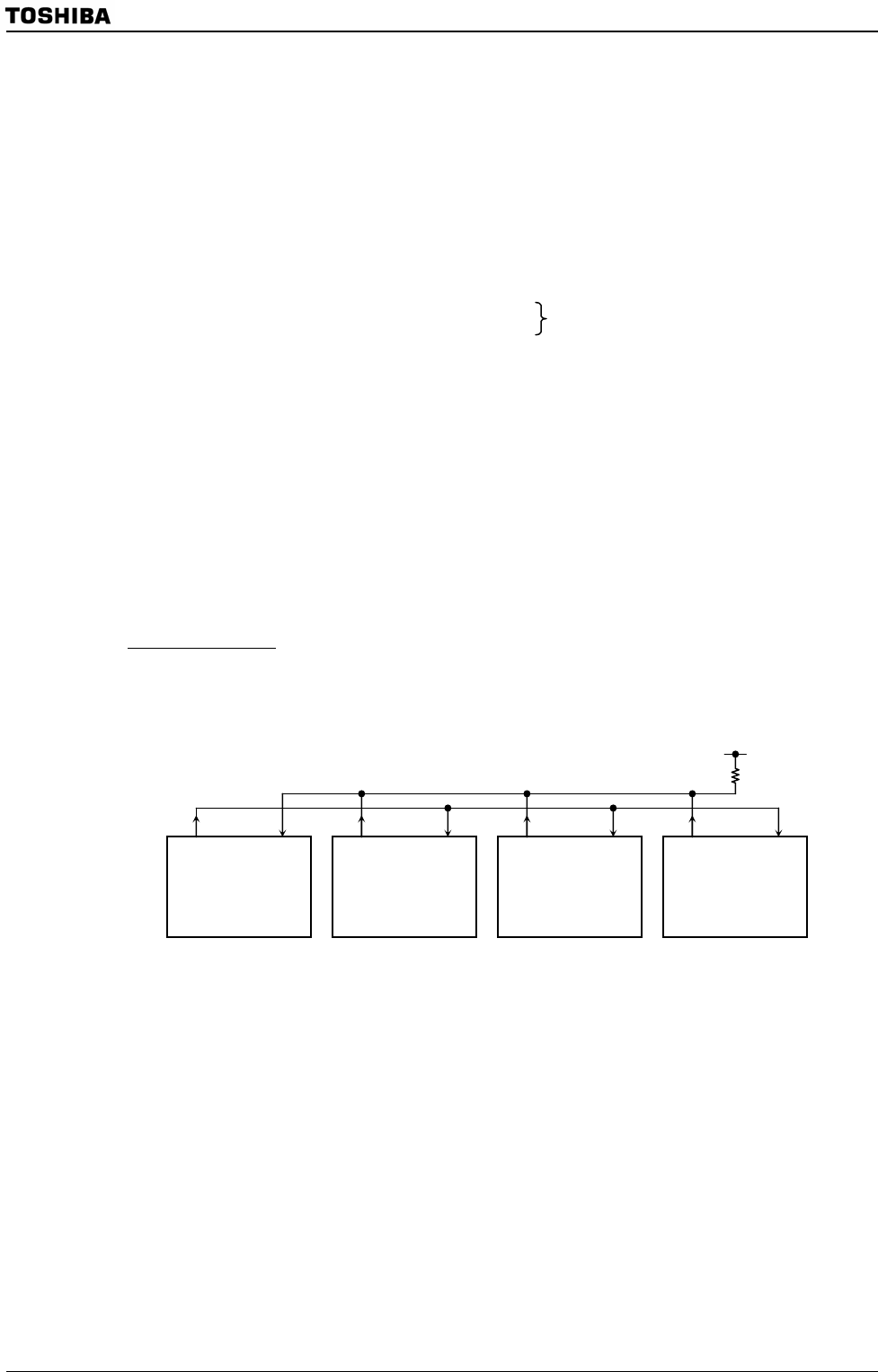
Wake-up function
In 9-Bit UART Mode, the wake-up function for slave controllers is enabled by
setting SC0MOD0<WU> to 1. The interrupt INTRX0 can only be generated
when<RB8> = 1.
Note: The TXD pin of each slave controller must be in Open-Drain Output Mode.
Figure 3.14.17 Serial Link using Wake-up function
TXD RXD
Master
TXD RXD
Slave1
TXD RXD
Slave 2
TXD RXD
Slave 3