


TMP92CZ26A
92CZ26A-322
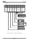
(6) The Receiving Buffers
To prevent Overrun errors, the Receiving Buffers are arranged in a double-buffer
structure.
Received data is stored one bit at a time in Receiving Buffer 1 (which is a shift
register). When 7 or 8 bits of data have been stored in Receiving Buffer 1, the stored
data is transferred to Receiving Buffer 2 (SC0BUF); these causes an INTRX0
interrupt to be generated. The CPU only reads Receiving Buffer 2 (SC0BUF). Even
before the CPU reads receiving Buffer 2 (SC0BUF), the received data can be stored in
Receiving Buffer 1. However, unless Receiving Buffer 2 (SC0BUF) is read before all
bits of the next data are received by Receiving Buffer 1, an overrun error occurs. If an
Overrun error occurs, the contents of Receiving Buffer 1 will be lost, although the
contents of Receiving Buffer 2 and SC0CR<RB8> will be preserved.
SC0CR<RB8> is used to store either the parity bit - added in 8-Bit UART Mode - or
the most significant bit (MSB) - in 9-Bit UART Mode.
In 9-Bit UART Mode the wake-up function for the slave controller is enabled by
setting SC0MOD0<WU> to 1; in this mode INTRX0 interrupts occur only when the
value of SC0CR<RB8> is 1.
SIO interrupt mode is selectable by the register SIMC.
Note1: The double buffer structure does not support SC0CR<RV08>.
Note2: If the CPU reads receive buffer 2 while data is being transferred from receive buffer 1 to receive buffer 2,
the data may not be read properly. To avoid this situation, a read of receive buffer 2 should be triggered by
a receive interrupt.
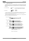
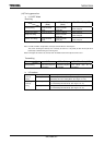
(7) Notes for Using Receive Interrupts
• Receive interrupts can be detected either in level or edge mode. For details, see the
description of the SIO/SEI receive interrupt mode select register SIMC in the
section on interrupts.
• When receive interrupts are set to level mode, once an interrupt occurs, the same
interrupt will occur repeatedly even after control has jumped to the interrupt
routine unless interrupts are disabled.
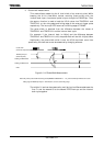
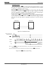
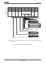
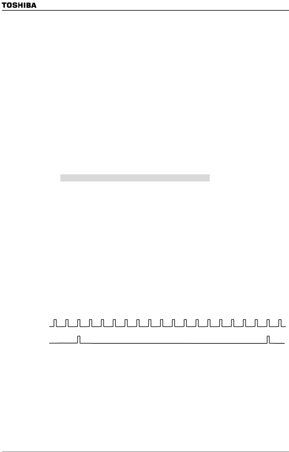
(8) Transmission counters
The transmission counter is a 4-bit binary counter which is used in UART Mode and
which, like the receiving counter, counts the SIOCLK clock pulses; a TXDCLK pulse is
generated every 16 SIOCLK clock pulses.
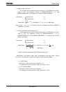
Figure 3.14.3 Generation of the transmission clock
15 16 1 2 3 4 5 6 7 8 9 10 11 12 13 14 15 16 1 2
SIOCLK
TXDCLK