


TMP92CZ26A
92CZ26A-84
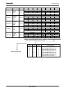
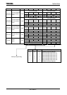
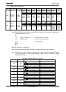
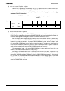
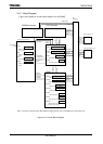
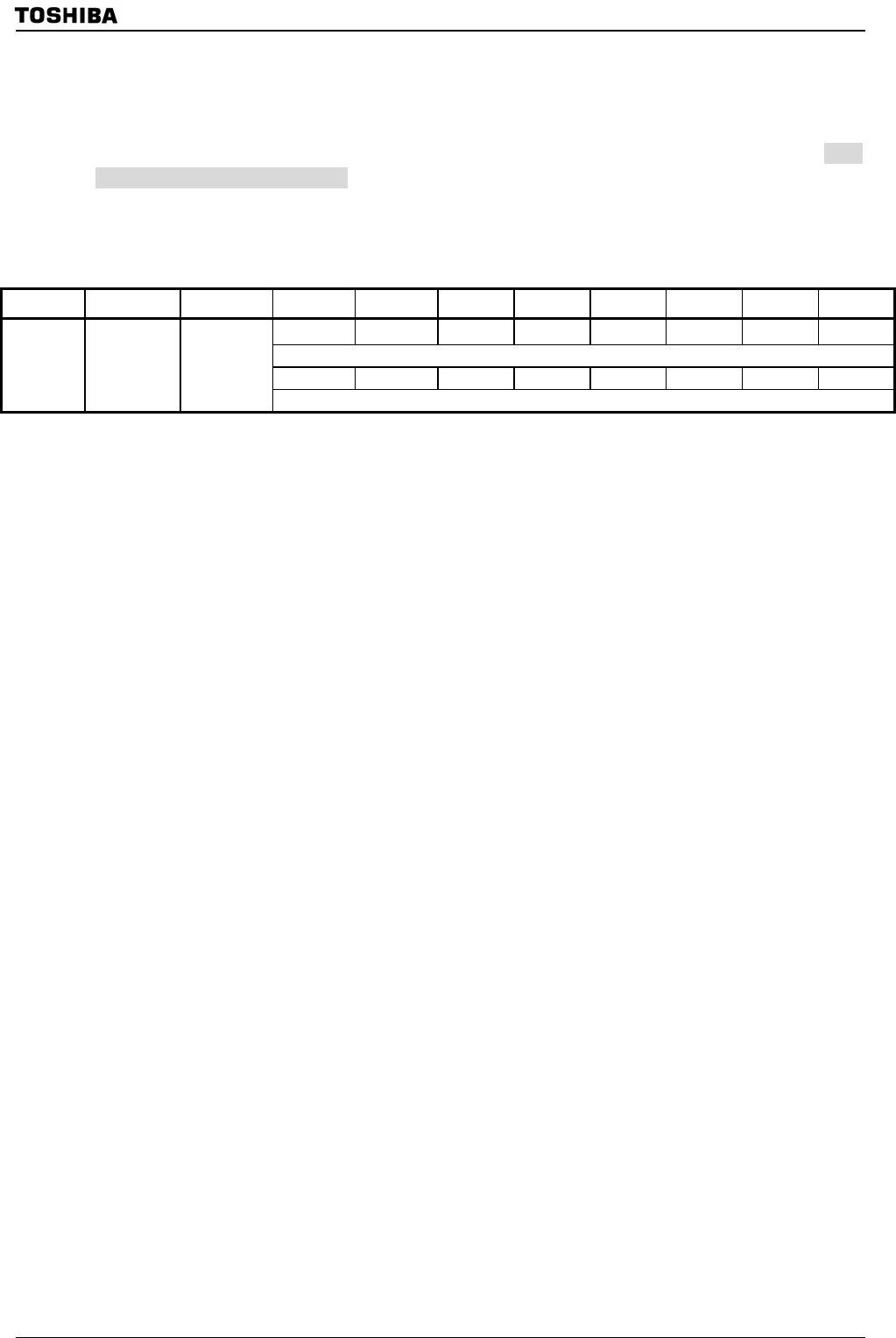
(4) Interrupt request flag clear register
The interrupt request flag is cleared by writing the appropriate micro DMA /HDMA start
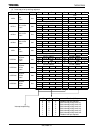
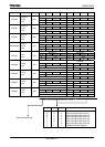
vector, as given in
Table 3.5.1 to the register INTCLR.
For example, to clear the interrupt flag INT0, perform the following register operation after
execution of the DI instruction.
INTCLR
←
0AH ; Clears interrupt request
flag INT0.
Symbol Name Address 7 6 5 4 3 2 1 0
CLRV7 CLRV6 CLRV5 CLRV4 CLRV3 CLRV2 CLRV1 CLRV0
W
0 0 0 0 0 0 0 0
INTCLR
Interrupt
clear
control
F8H
(Prohibit
RMW)
Interrupt vector
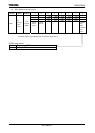
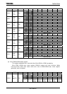
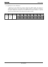
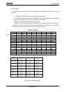
(5) Micro DMA start vector registers
These registers assign micro DMA /HDMA processing to sets which source corresponds to
DMA. The interrupt source whose micro DMA /HDMA start vector value matches the vector set
in one of these registers is designated as the micro DMA /HDMA start source.
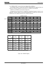
When the micro DMA transfer counter (DMACn) or HDMA transfer counter B (HDMACBn)
value reaches “0”, the micro DMA /HDMA transfer end interrupt corresponding to the channel
is sent to the interrupt controller, the micro DMA /HDMA start vector register is cleared, and
the micro DMA /HDMA start source for the channel is cleared. Therefore, in order for micro
DMA /HDMA processing to continue, the micro DMA /HDMA start vector register must be set
again during processing of the micro DMA /HDMA transfer end interrupt.
If the same vector is set in the micro DMA /HDMA start vector registers of more than one
channel, the lowest numbered channel takes priority.
Accordingly, if the same vector is set in the micro DMA /HDMA start vector registers for two
different channels, the interrupt generated on the lower-numbered channel is executed until
micro DMA /HDMA transfer is complete. If the micro DMA /HDMA start vector for this channel
has not been set in the channel’s micro DMA /HDMA start vector register again, micro DMA
/HDMA transfer for the higher-numbered channel will be commenced. (This process is known
as micro DMA /HDMA chaining.)