


TMP92CZ26A
92CZ26A-336
(2) Mode 1 (7-bit UART Mode)
7-Bit UART Mode is selected by setting the Serial Channel Mode Register
SC0MOD0<SM1:0> field to 01.
In this mode a parity bit can be added. Use of a parity bit is enabled or disabled by the
setting of the Serial Channel Control Register SC0CR<PE> bit; whether even parity
or odd parity will be used is determined by the SC0CR<EVEN> setting when
SC0CR<PE> is set to 1 (enabled).
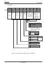
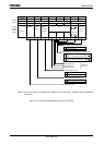
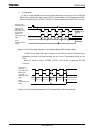
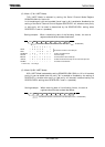
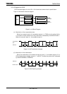
Setting example: When transmitting data of the following format, the control
registers should be set as described below.
7 6 5 4 3 2 1 0
P9CR
←
X X X X X
− −
1
P9FC
← − −
X X X
−
X1
Set P90 to function as the TXD0 pin.
SC0MOD0
←
X 0
−
X 0 1 0 1 Select 7-bit UART mode.
SC0CR
←
−
1 1
− − − − −
Add even parity.
BR0CR
←
0 0 1 0 1 0 0 0 Set the transfer rate to 2400 bps.
INTES0
←
X 1 0 0 X
0 0 0 Enable the INTTX0 interrupt and set it to interrupt level 4.
SC0BUF
←
* * * * * * * *
Set data for transmission.
X: Don't care, −: No change
(3) Mode 2 (8-Bit UART Mode)
8-Bit UART Mode is selected by setting SC0MOD0<SM1,SM0> to 10. In this mode a
parity bit can be added (use of a parity bit is enabled or disabled by the setting of
SC0CR<PE>); whether even parity or odd parity will be used is determined by the
SC0CR<EVEN> setting when SC0CR<PE> is set to 1 (enabled).
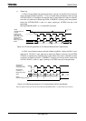
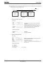
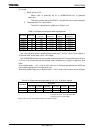
Setting example: When receiving data of the following format, the control
registers should be set as described below.
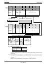
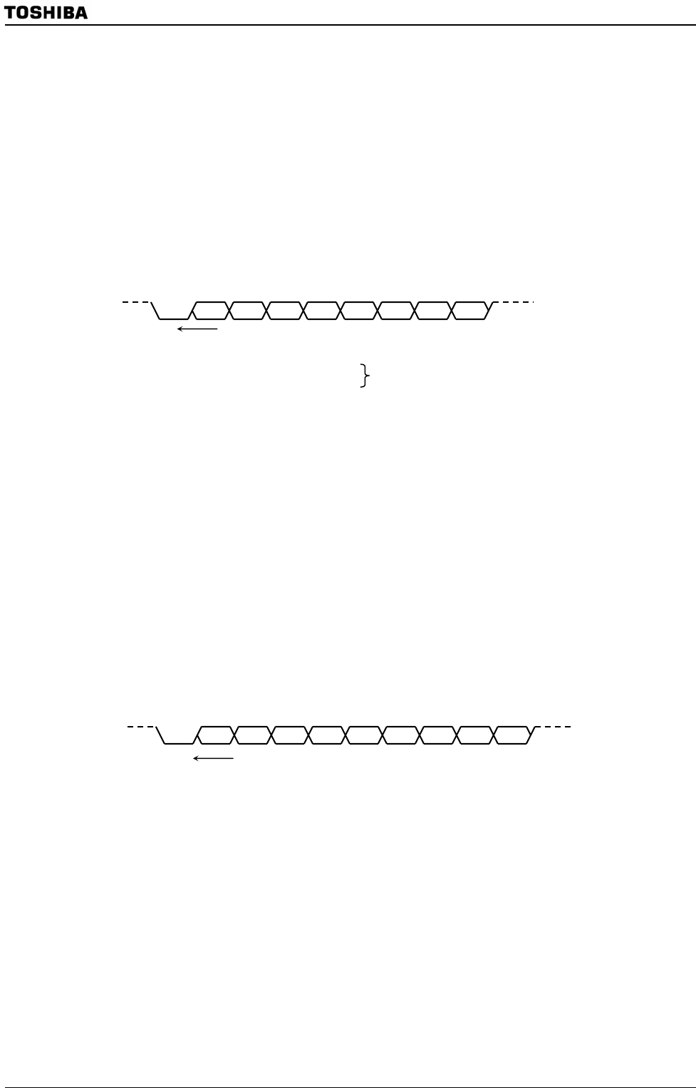
Start Bit0 1
2
3456
Even
parity
Transmission direction (Transmission rate: 2400 bps at f
SYS
= 19.6608 MHz)
Transmission direction (Transmission rate: 9600 bps at f
SYS
= 19.6608 MHz)
Start Bit0 1 2 3 4 5 6
Odd
parity
Stop 7