


TMP92CZ26A
92CZ26A-651
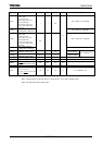
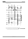
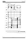
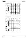
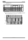
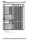
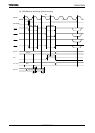
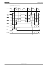
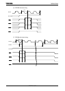
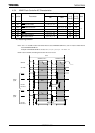
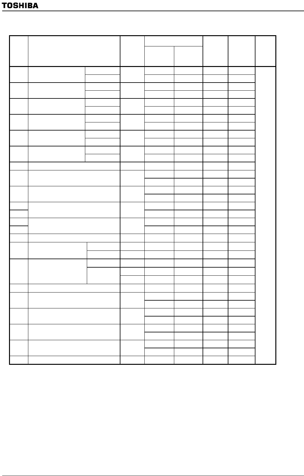
4.3.3 SDRAM controller AC Characteristics
Variable
Parameter Symbol
Min Max
80 MHz 60 MHz Unit
<STRC[2:0]>=000
T 12.5 16.6
1
Ref/Active to ref/active
command period
<STRC[2:0]>=110
t
RC
7T 87.5 116.2
<STRC[2:0]>=000
2T 12210 25.0 33.2
2
Active to precharge
command period
<STRC[2:0]>=110
t
RAS
7T 87.5 116.2
<STRCD>=0
T 12.5 16.6
3
Active to read/write
command delay time
<STRCD>=1
t
RCD
2T 25.0 33.2
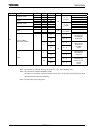
<STRP>=0
T 12.5 16.6
4
Precharge to active
command period
<STRP>=1
t
RP
2T 25.0 33.2
<STRC[2:0]>=000
3T 37.5 49.8
5
Active to active
command period
<STRC[2:0]>=110
t
RRD
7T 87.5 116.2
<STWR>=0
T 12.5 16.6
6 Write recovery time
<STWR>=1
t
WR
2T 25.0 33.2
7 CLK cycle time
t
CK
T 12.5 16.6
0.5T − 5
−
3.3
8 CLK high level width
t
CH
0.5T
− 3 3.25
−
0.5T − 5
−
3.3
9 CLK low level width
t
CL
0.5T
− 3 3.25
−
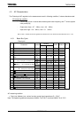
10-1a T − 16
−
0.6
10-1b
Access time from CLK(CL
* =2)
<SRDS>=0(Read data shift OFF)
t
AC
T
− 16 - 3.5
−
10-2a T − 6.5
−
10.1
10-2b
Access time from CLK(CL
* =2)
<SRDS>=1(Read data shift ON)
t
AC
T
− 6.5 6
−
11 Output data hold time
t
OH
0 0 0
1Word/Single
t
DS
0.5T
− 4 2.25 3.3
12 Data-in set-up time
Burst
t
DS
0.5T
− 4 2.25 3.3
1Word/Single
t
DH
T
− 10 2.5 6.6
t
DH
0.5T
− 6
−
2.3
13 Data-in hold time
Burst
t
DH
0.5T
− 4 2.25
−
14 Address set-up time
t
AS
0.5T
− 4 2.25 4.3
0.5T − 6
−
2.3
15 Address hold time
t
AH
0.5T
− 4 2.25
−
0.5T − 5
−
3.3
16 CKE set-up time
t
CKS
0.5T
− 3 3.25
−
0.5T − 5
−
3.3
17 Command set-up time
t
CMS
0.5T
− 3 3.25
−
0.5T − 6
−
2.3
18 Command hold time
t
CMH
0.5T
− 4 2.25
−
19 Mode register set cycle time
t
RSC
T 12.5 16.6
ns
*CL: CAS latency
AC measuring condition
SDCLK pin C
L
= 30 pF, Other pins C
L
= 50 pF