


TMP92CZ26A
92CZ26A-273
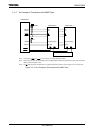
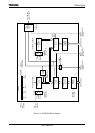
(4) Comparator (CP0, CP1)
The comparator compares the value in an up counter with the value set in a timer
register. If they match, the up counter is cleared to 0 and an interrupt signal (INTTA0
or INTTA1) is generated. If timer flip-flop inversion is enabled, the timer flip-flop is
inverted at the same time.
Note: If a value smaller than the up-counter value is written to the timer register while the timer is counting up, this will
cause the timer to overflow and an interrupt cannot be generated at the expected time. (The value in the timer
register canbe changed without any problem if the new value is larger than the up-counter value.) In 16-bit
interval timer mode, be sure to write to both TA0REG and TA1REG in this order (16 bits in total), The compare
circuit will not function if only the lower 8 bits are set.
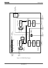
(5) Timer flip-flop (TA1FF)
The timer flip-flop (TA1FF) is a flip-flop inverted by the match detects signal (8-bit
comparator output) of each interval timer.
Whether inversion is enabled or disabled is determined by the setting of the bit
TA1FFCR<TA1FFIE> in the timer flip-flops control register. A reset clears the value
of TA1FF to 0. Writing 01 or 10 to TA1FFCR<TA1FFC1:0> sets TA1FF to 0 or 1.
Writing 00 to these bits inverts the value of TA1FF. (This is known as software
inversion.)
The TA1FF signal is output via the TA1OUT pin. When this pin is used as the timer
output, the timer flip-flop should be set beforehand using the port function registers.
The condition for TA1FF inversion varies with mode as shown below
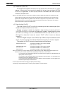
8-bit interval timer mode : UC0 matches TA0REG or UC1 matches TA1REG
(Select either one of the two)
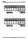
16-bit interval timer mode : UC0 matches TA0REG or UC1 matches TA1REG
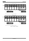
80bit PWM mode
: UC0 matches TA0REG or a 2
n
overflow occurs
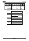
8-bit PPG mode : UC0 matches TA0REG or UC0 matches TA1REG
Note: If an inversion by the match-detect signal and a setting change via the TMRA1 flip-flopcontrol register occur
simultaneously, the resultant operation varies depending on the situation, as shown below.
If an inversion by the match-detect signal and an inversion via the register occur simultaneously, the
flip-flop will be inverted only once.
If an inversion by the match-detect signal and an attempt to set the flip-flop to 1 via the register occur
simultaneously, the timer flip-flop will be set to 1.
If an inversion by the match-detect signal and an attempt to clear the flip-flop to 0 via the register occur
simultaneously the flip-flop will be cleared to 1.
Be sure to stop the timer before changing the flip-flop incersion setting.
If the setting is chaged while the timer is counting, proper operation cannot be obtained.