


TMP92CZ26A
92CZ26A-72
3.5.2 Micro DMA processing
In addition to general-purpose interrupt processing, the TMP92CZ26A also includes a
micro DMA function and HDMA function. This section explains about Micro DMA function.
For the HDMA function, please refer 3.23 DMA controller.
Micro DMA processing for interrupt requests set by micro DMA is performed at the
highest priority level for maskable interrupts (Level 6), regardless of the priority level of
the interrupt source.
Because the micro DMA function has been implemented with the cooperative operation
of CPU, when CPU is a state of standby (IDLE2,IDLE1,STOP) by HALT instruction, the
requirement of micro DMA will be ignored (Pending).
Micro DMA is supported 8 channels and can be transferred continuously by specifying
the micro DMA burst function in the following.
Note: When using the micro DMA transfer end interrupt, always write “1” to bit 7 of SIMC register.
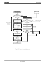
(1) Micro DMA operation
When an interrupt request is generated by an interrupt source that specified by the
micro DMA /HDMA start vector register, and Micro DMA start is specified by DMA
selection register, the micro DMA triggers a micro DMA request to the CPU at
interrupt priority level 6 and starts processing the request. When IFF = 7, Micro DMA
request cannot be accepted.
The 8 micro DMA channels allow micro DMA processing to be set for up to 8 types of
interrupt at once.
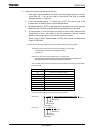
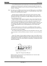
When micro DMA is accepted, the interrupt request flip-flop assigned to that
channel is cleared. Data in 1byte or 2byte or4byte blocks is automatically transferred
at once from the transfer source address to the transfer destination address set in the
control register, and the transfer counter is decremented by “1”. If the value of the
counter after it has been decremented is not “0”, DMA processing ends with no change
in the value of the micro DMA start vector register. If the value of the decremented
counter is “0”, a micro DMA transfer end interrupt (INTTC0 to INTTC7) is sent from
the CPU to the interrupt controller.
In addition, the micro DMA /HDMA start vector register is cleared to “0”, the next
micro DMA operation is disabled and micro DMA processing terminates.
If an interrupt request is triggered for the interrupt source in use during the
interval between the time at which the micro DMA /HDMA start vector is cleared and
the next setting, general-purpose interrupt processing is performed at the interrupt
level set. Therefore, if the interrupt is only being used to initiate micro DMA /HDMA
(and not as a general-purpose interrupt), the interrupt level should first be set to 0
(e.g., interrupt requests should be disabled).
If micro DMA and general-purpose interrupts are being used together as described
above, the level of the interrupt which is being used to initiate micro DMA processing
should first be set to a lower value than all the other interrupt levels. In this case,
edge-triggered interrupts are the only kinds of general interrupts which can be
accepted.