


TMP92CZ26A
92CZ26A-200
3.8.5 Internal Boot ROM Control
This section describes about built-in boot ROM.
For the specification of S/W in boot ROM, refer to the section 3.4 boot ROM.
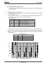
(1) BOOT mode
BOOT mode is started by following AM1 and AM0 pins condition with reset.
AM1 AM0 Start mode
0 0 Don’t use this setting
0 1 Start with 16-bit data bus
1 0 Don’t use this setting
1 1 Start with boot (32-bit internal MROM)
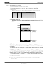
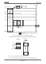
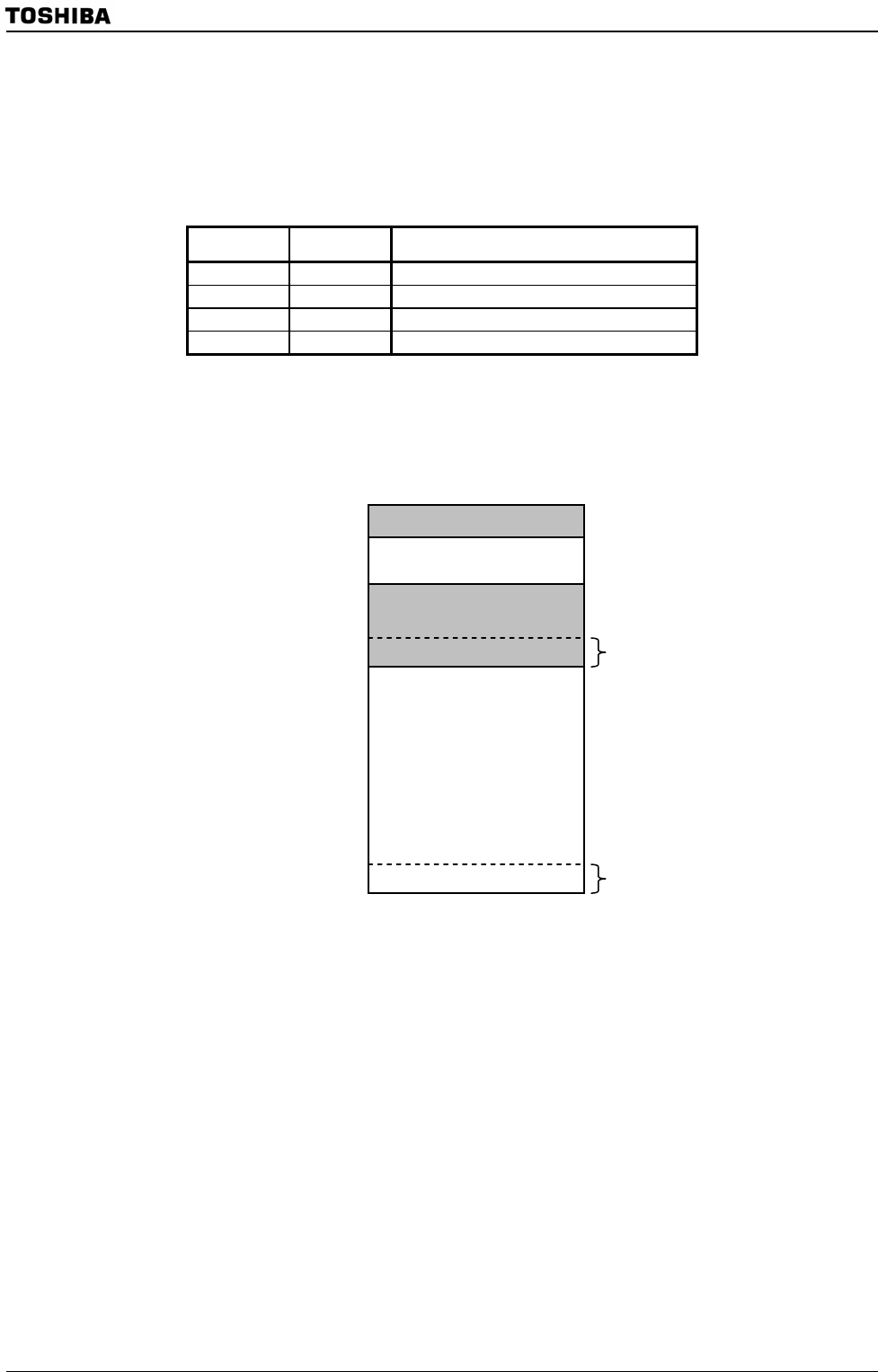
(2) Boot ROM memory map
Boot ROM is consist of 8-Kbyte masked ROM and assigned 3FE000H to 3FFFFFH
address.
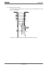
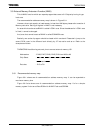
(3) Reset/interrupt address conversion circuit
Originally, reset/interrupt vector area is assigned FFFF00H to FFFFEFH ((A) area) in
TLCS-900/H1.
But because boot ROM is assigned to another area, reset/interrupt vector address
conversion circuit is prepared.
In BOOT mode, reset/interrupt vector area is assigned 3FFF00H to 3FFFEFH ((B) area)
area by it. And after boot sequence, its area can be changed to (A) area by setting
BROMCR<VACE> to “0”. So, (A) area can be used only for application system program.
This BROMCR<VACE> is initialized to “1” in BOOT mode. At another starting mode,
this register has no meaning.
Note: The last 16-byte area (FFFFF0H to FFFFFFH) is reserved for an emulator. So, this area is not changed
by <VACE> register.
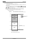
Internal I/O , RAM
Internal boot ROM
(8 Kbytes)
04A000H
400000H
3FFF00H
FFFF00H
(B) Reset/Interrupt
Vector area
(256 bytes)
3FE000H
(A) Reset/Interrupt
Vector area
(256 bytes)
000000H