


TMP92CZ26A
92CZ26A-87
(8) Notes
The instruction execution unit and the bus interface unit in this CPU operate
independently. Therefore, if immediately before an interrupt is generated, the CPU fetches
an instruction which clears the corresponding interrupt request flag, the CPU may execute
this instruction in between accepting the interrupt and reading the interrupt vector. In this
case, the CPU will read the default vector 0004H and jump to interrupt vector address
FFFF04H.
To avoid this, an instruction which clears an interrupt request flag should always be
preceded by a DI instruction. And in the case of setting an interrupt enable again by EI
instruction after the execution of clearing instruction, execute EI instruction after clearing
and more than 3-instructions (e.g., “NOP” × 3 times). If placed EI instruction without
waiting NOP instruction after execution of clearing instruction, interrupt will be enable
before request flag is cleared.
In the case of changing the value of the interrupt mask register <IFF2:0> by execution of
POP SR instruction, disable an interrupt by DI instruction before execution of POP SR
instruction.
In addition, please note that the following two circuits are exceptional and demand
special attention.
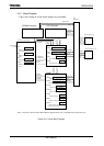
INT0 level mode
In level mode INT0 is not an edge-triggered interrupt. Hence, in level mode the
interrupt request flip-flop for INT0 does not function. The peripheral interrupt
request passes through the S input of the flip-flop and becomes the Q output. If the
interrupt input mode is changed from edge mode to level mode, the interrupt
request flag is cleared automatically.
If the CPU enters the interrupt response sequence as a result of INT0 going from 0
to 1, INT0 must then be held at 1 until the interrupt response sequence has been
completed. If INT0 is set to level mode so as to release a halt state, INT0 must be
held at 1 from the time INT0 changes from 0 to 1 until the halt state is released.
(Hence, it is necessary to ensure that input noise is not interpreted as a 0, causing
INT0 to revert to 0 before the halt state has been released.)
When the mode changes from level mode to edge mode, interrupt request flags
which were set in level mode will not be cleared. Interrupt request flags must be
cleared using the following sequence.
DI
LD (IIMC0), 00H ; Switches from level to edge.
LD (INTCLR), 0AH ; Clears interrupt request flag.
NOP ; Wait EI execution
NOP
NOP
EI
INTRX
In level mode (The register SIMC<IRxLE> set to “1”), the interrupt request flip-flop
can only be cleared by a reset or by reading the serial channel receive buffer. It
cannot be cleared by an instruction.
Note: The following instructions or pin input state changes are equivalent to instructions which
clear the interrupt request flag.
INT0: Instructions which switch to level mode after an interrupt request has been
generated in edge mode.
The pin input changes from high to low after an interrupt request has been
generated in level mode. (“H” → “L”)
INTRX: Instructions which read the receive buffer.