


TMP92CZ26A
92CZ26A-532
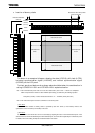
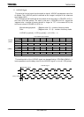
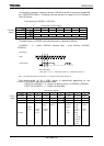
The number of pulses in the front dummy LHSYNC (vertical front porch) is specified
by LCDPRVSP<PLV6:0>. This delay time can be set in a range of 0 to 127 pulses of
the LCP0 clock.
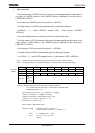
Front dummy LHSYNC = <PLV6:0>
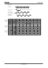
LCD LVSYNC Pre Pulse Register
7 6 5 4 3 2 1 0
bit Symbol PLV6 PLV5 PLV4 PLV3 PLV2 PLV1 PLV0
Read/Write W
After reset 0 0 0 0 0 0 0
Function Front dummy LVSYNC (bits 6-0)
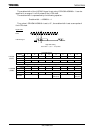
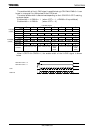
The back dummy LHSYNC (vertical back porch) is defined as follows:
(<LVP9:0> + 1) − (valid LHSYNC: common size) − (front dummy LHSYNC:
<PLV6:0>)
Note: The vertical back porch must be set to “1” or longer in all the cases (STN/TFT).
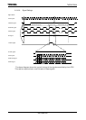
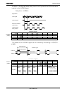
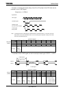
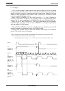
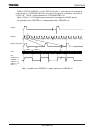
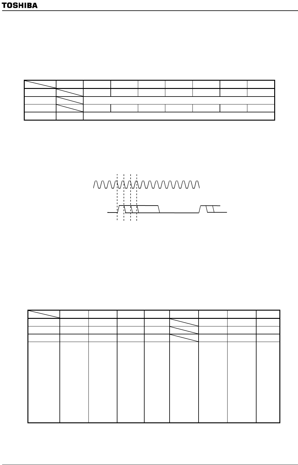
The enable width of the LLOAD signal is determined depending on the
LCDCTL0<LCP0OC> setting, as shown below.
LCDCTL0<LCP0OC> = 0 : Output at setting value in (LCDDLW) <LDW9:0>
LCDCTL0<LCP0OC> = 1 : Output at valid data
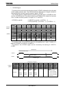
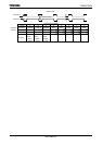
LCD Control 0 Register
7 6 5 4 3 2 1 0
bit Symbol PIPE ALL0 FRMON
–
DLS LCP0OC START
Read/Write R/W R/W R/W R/W R/W R/W R/W
After reset 0 0 0 0 0 0 0
Function
PIP function
0: Disable
1: Enable
Segment
data
0: Normal
1: Always
output “0”
Frame divide
setting
0: Disable
1: Enable
Always
write “0”
FR signal
LCP0/Line
selection
0: Line
1: LCP0
LCP0 (Note)
0: Always
output
1: At valid
d
ata onl
y
LLOAD
width
0: At setting
in register
1: At valid
data only
LCDC
operation
0: Stop
1: Start
Note: When select STN mode, LCP0 is output at valid data only regardless of the setting of <LCP0OC> bit.
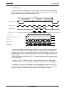
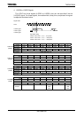
LCP0
Signal Name
LLOAD signal
High width setting
LCP0 clock = 1, 2, 3 … 1023 pulses (<PDT>=0) / 1024 pulses (<PDT>=1)
LCDPRVSP
(028EH)
LCDCTL0
(
0285H
)