TMP92CZ26A
92CZ26A-338
Protocol
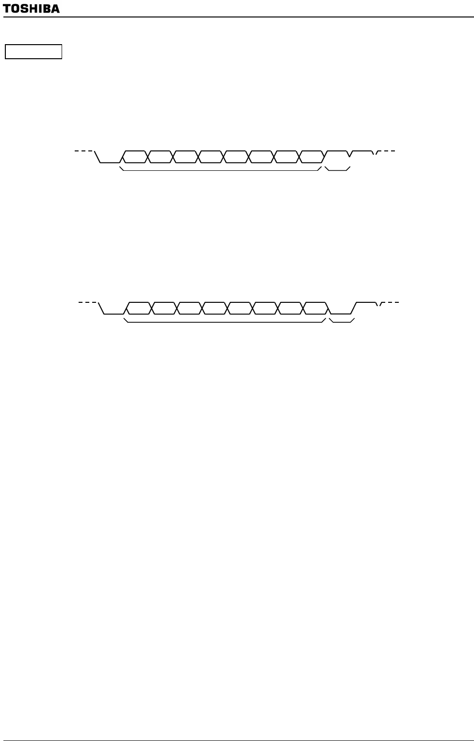
1. Select 9-Bit UART Mode on the master and slave controllers.
2. Set the SC0MOD0<WU> bit on each slave controller to 1 to enable data receiving.
3. The master controller transmits data one frame at a time. Each frame includes an 8-bit
select code which identifies a slave controller. The MSB (bit 8) of the data (<TB8>) is
set to 1.
4. Each slave controller receives the above frame. Each controller checks the above select
code against its own select code. The controller whose code matches clears its <WU>
bit to 0.
5. The master controller transmits data to the specified slave controller (the controller
whose SC0MOD0<WU> bit has been cleared to 0). The MSB (bit 8) of the data
(<TB8>) is cleared to 0.
6. The other slave controllers (whose <WU> bits remain at 1) ignore the received data
because their MSBs (bit 8 or <RB8>) are set to 0, disabling INTRX0 interrupts.
The slave controller whose <WU> bit = 0 can also transmit to the master controller. In
this way it can signal the master controller that the data transmission from the
master controller has been completed.
Start Bit0 1 2 3 4 5 6
Select code of slave controller
7
Stop
8
“1”
Data “0”
Start Bit0 1 2 3 4 5 6
7
Stop
Bit8


